Serial ATA (SATA)
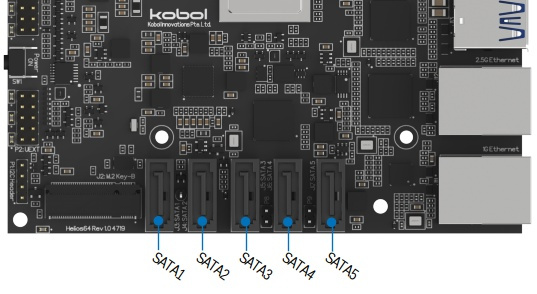
Helios64 uses the JMicron JMB585 Serial ATA (SATA) controller to provide 5x SATA 3.0 ports.
The SATA Controller is connected to RK3399 SoC via 2x lanes PCIe 2.0 offering 10GT/s (8Gbps) of bandwidth.
SATA Controller Features
- 5 SATA ports,
- Command-based and FIS-based for Port Multiplier,
- Compliance with SATA Specification Revision 3.2,
- AHCI mode and IDE programming interface,
- Native Command Queue (NCQ),
- SATA link power saving mode (partial and slumber),
- SATA plug-in detection capable,
- Drive power control and staggered spin-up,
- SATA Partial / Slumber power management state.
SATA Controller Diagram
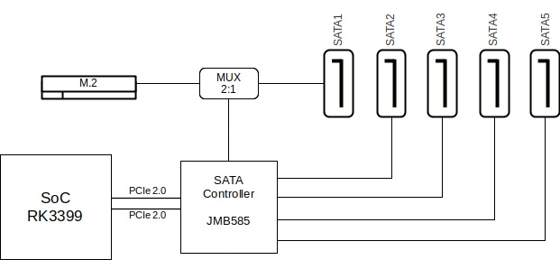
The above diagram shows the 2:1 MUX between SATA Port 1 and the M.2 connector. The M.2 SATA bus is shared with SATA Port 1, therefore if you install an M.2 SATA SSD card, SATA Port 1 (J3) will automatically get disabled.
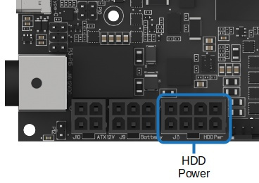
HDD Power
Helios64 provides on-board HDD power to supply up to 5x HDDs via header J8.
The power delivery of the HDDs is devided into two group:
- HDD Rail A (Max. 3x Drives)
- HDD Rail B (Max. 2x Drives)
Helios64 implements a power staggering approach where HDD Rail A will be powered up first, then few seconds later HDD Rail B will be powered up. This power control scenario is performed to reduce the inrush current during disk spin-up.
Note
The power staggering mechanism is not user configurable. It is done by the bootloader.
J8 Pinout
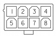
| Pin | Signal Name |
|---|---|
| 1 | 12V HDD Rail A |
| 2 | 12V HDD Rail B |
| 3 | 5V HDD Rail A |
| 4 | 5V HDD Rail B |
| 5 | GND |
| 6 | GND |
| 7 | GND |
| 8 | GND |
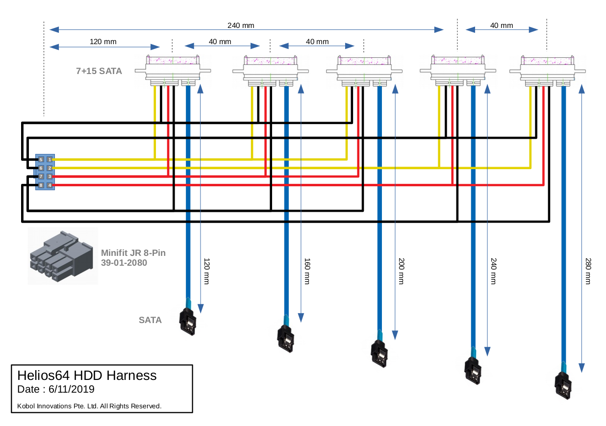
HDD/SSD Harness
As part of Helios64 official enclosure, an HDD/SSD harness is provided to connected both SATA + Power signals between Helios64 board and the 5x HDD slots.
Below the wiring diagram: