I2C
Helios64 supports I2C bus for low-speed communication between devices like microcontrollers, EEPROMs, A/D and D/A converters, I/O interfaces and other similar peripherals. In order to communicate with each I2C slave device you will need an address and communication scenario.
I2C bus on Helios64 / RK3399
The I2C controller on RK3399 supports following features:
- 9 on-chip I2C controllers
- Multi-master I2C operation
- Support 7bits and 10bits address mode
- Serial 8bits oriented and bidirectional data transfers can be made
- Software programmable clock frequency
- Data on the I2C-bus can be transferred at rates of up to 100 kbit/s in the Standardmode, up to 400 kbit/s in the Fast-mode or up to 1 Mbit/s in Fast-mode Plus
Note: In the implementation we divided the I2C controller into 2 categories:
- Internal Bus, reserved for the system
- Externel Bus, allocated for user application
Internal Bus
Warning
Theses buses and addresses should not be accessed directly by user. Incorrect configuration can damage the board.
Bus 0:
| Slave | Address | Description |
|---|---|---|
| RK808-D | 0x1b | |
| SYR837 | 0x40 | |
| SYR838 | 0x41 |
Bus 2:
| Slave | Address | Description |
|---|---|---|
| NCT75 | 0x4c | |
| PCA9655 | 0x20 |
Bus 4:
| Slave | Address | Description |
|---|---|---|
| FUSB302 | 0x22 |
Above list also includes buses number 1,3,5 which are reserved for system use, therefore not accessible to the user.
External Bus
Helios64 exposes Bus number 7 and 8 respectively on P2 and P1 headers.
All the I2C buses on the board are using voltage level of 3.3V. Note that Helios64 is integrated with level translator and pull up resistor.
Please take caution of the reserved address when you use the I2C interface, below is the reserved address list:
| Slave Address | R/W Bit | Description |
|---|---|---|
| 000 0000 | 0 | General call address |
| 000 0000 | 1 | START byte(1) |
| 000 0001 | X | CBUS address(2) |
| 000 0010 | X | Reserved for different bus format (3) |
| 000 0011 | X | Reserved for future purposes |
| 000 01XX | X | Hs-mode master code |
| 111 10XX | X | 10-bit slave addressing |
| 111 11XX | X | Reserved for future purposes |
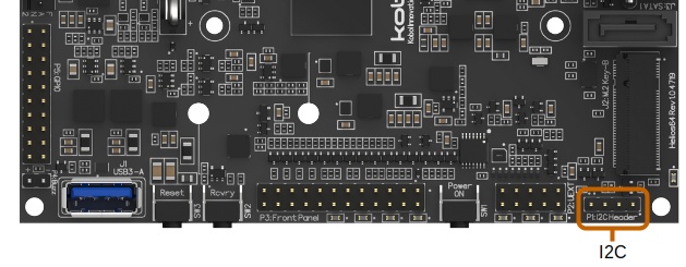
I2C Header (P1)
Helios64 board exposes I2C Bus 8 on header P1.
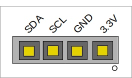
This I2C device works with 3 pin bus (SDA, SCL, and GND), and also in band addressing. Below is the header pin-out:
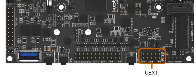
UEXT Header (P2)
The I2C Bus 7 can be found on the UEXT header (P2).
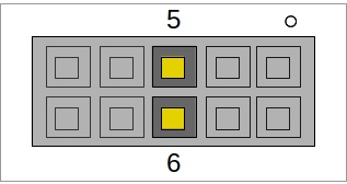
Below is the full pinout of the UEXT header:
| Pin No | Description |
|---|---|
| 1 | 3.3V |
| 2 | GND |
| 3 | TXD (UART) |
| 4 | RXD (UART) |
| 5 | SCL (I2C) |
| 6 | SDA (I2C) |
| 7 | MISO (SPI) |
| 8 | MOSI (SPI) |
| 9 | SCK (SPI) |
| 10 | SSEL (SPI) |
Usage under Linux
Below table list the I2C external bus device name as detected under Linux:
| Bus number | Device Block | Description |
|---|---|---|
| 7 | /dev/i2c-7 | |
| 8 | /dev/i2c-8 |
Checking the I2C Communication under linux
In order to communicate with the I2C devices, first we need to identify the I2C bus. By performing scan you can see whether the system can detect device.
- Install the Linux i2c tools.
$ sudo apt-get install i2c-tools
- Use i2cdetect tool to scan I2C Bus 8.
root@helios64:~# i2cdetect -y 8

     0  1  2  3  4  5  6  7  8  9  a  b  c  d  e  f
00:          -- -- -- -- -- -- -- -- -- -- -- -- --
10: -- -- -- -- -- -- -- -- -- -- -- -- -- -- -- --
20: -- -- -- -- -- -- -- -- -- -- -- -- -- -- -- --
30: -- -- -- -- -- -- -- -- -- -- -- -- 3c -- -- --
40: -- -- -- -- -- -- -- -- -- -- -- -- -- -- -- --
50: -- -- -- -- -- -- -- -- -- -- -- -- -- -- -- --
60: -- -- -- -- -- -- -- -- -- -- -- -- -- -- -- --
70: -- -- -- -- -- -- -- --
Here we can see there is a device detected at the address 0x3c. If you have connected more than just one I2C device on the P1 header, there will be more devices with different addresses detected on the bus.