PWM (Fan)
Warning
Always POWER OFF the system before plug/unplug the fan. Failed to do so could damage the controlling GPIO due to power surge.
PWM Introduction
PWM, or pulse width modulation is a technique which allows us to adjust the average value of the voltage that’s going to the electronic device by varying duty cycle of the power at a fast rate.
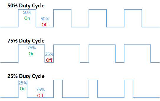
The term duty cycle describes the proportion of 'on' time to the regular interval or 'period' of time; a low duty cycle corresponds to low power, because the power is off for most of the time. Duty cycle is expressed in percent, 100% being fully on. When a digital signal is on half of the time and off the other half of the time, the digital signal has a duty cycle of 50% and resembles a "square" wave. When a digital signal spends more time in the on state than the off state, it has a duty cycle of >50%. When a digital signal spends more time in the off state than the on state, it has a duty cycle of <50%. Here is a pictorial that illustrates these three scenarios:
PWM Fan Implementation
Type-A
Type-B
Type-C
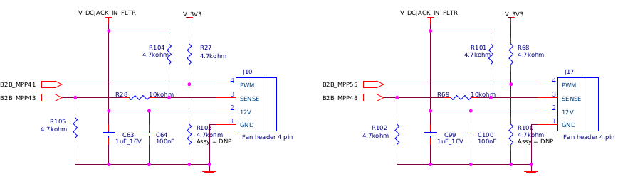
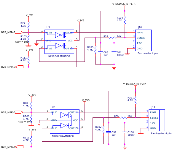
Helios4 Fan Control Schematic
Board Rev 1.1
Remarks
| Description | Header J10 | Header J17 | Remarks |
|---|---|---|---|
| PWM pin | gpio41 | gpio55 | 3.3V pull up fan ONLY! Early generation of 4-wire pwm fan may use 5V pull-up |
| SENSE pin | gpio43 | gpio48 | SENSE pin is not implemented yet |
| PWM Frequency | 25 kHz | 25 kHz | defined in device tree |
Board Rev 1.2
Remarks
| Description | Header J10 | Header J17 | Remarks |
|---|---|---|---|
| PWM pin | gpio41 | gpio55 | 5V tolerant |
| SENSE pin | gpio43 | gpio48 | SENSE pin is not implemented yet |
| PWM Frequency | 25 kHz | 25 kHz | defined in device tree |
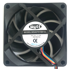
Bundled Fan

Connector Pinout
| Pin | Function | Wire Color |
|---|---|---|
| 1 | GND | Black |
| 2 | 12V | Red |
| 3 | Sense | Yellow |
| 4 | Control | Blue |
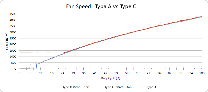
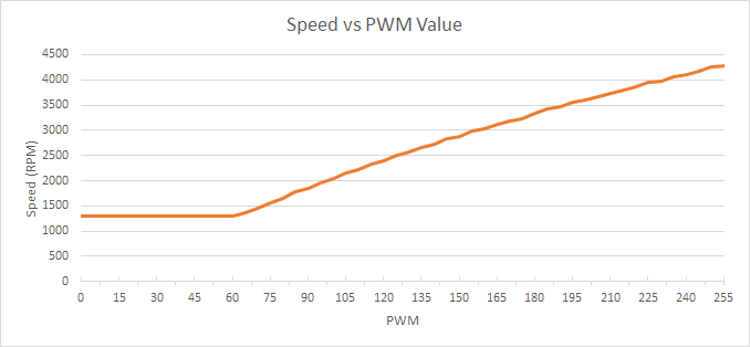
Type-A Fan (Batch 1 & 3)
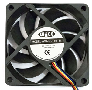
Fan Specification
| Parameter | Value | Unit | Remarks |
|---|---|---|---|
| Maximum Speed | 4200 | RPM | @ duty cycle 98% |
| Minimum Speed | 1200 | RPM | @ duty cycle 24% |
| Shut off | No | Not Supported | |
| Implementation Type | A |
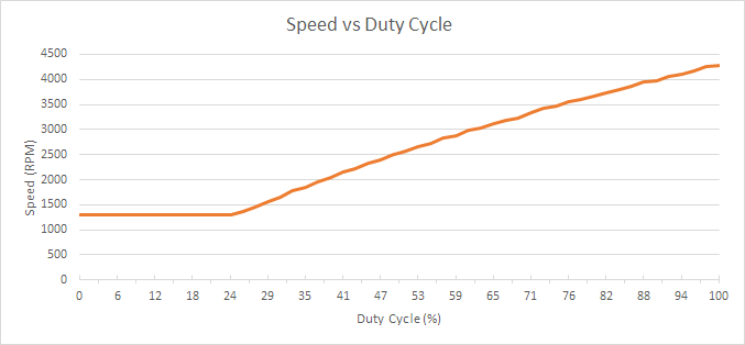
Info
Duty cycle data is converted from Linux PWM
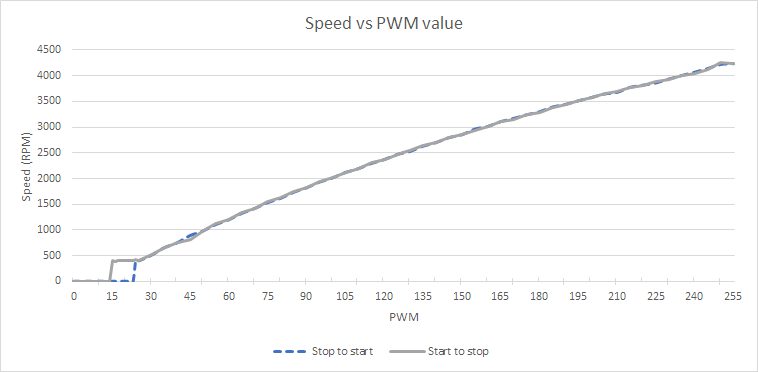
Type-C Fan (Batch 2)
Fan Specification
| Parameter | Value | Unit | Remarks |
|---|---|---|---|
| Maximum Speed | 4200 | RPM | @ duty cycle 98% |
| Minimum Speed | 400 | RPM | @ duty cycle 10% |
| Shut off | Yes | duty cycle <= 5.5% and restart @ duty cycle > 9% | |
| Implementation Type | C |
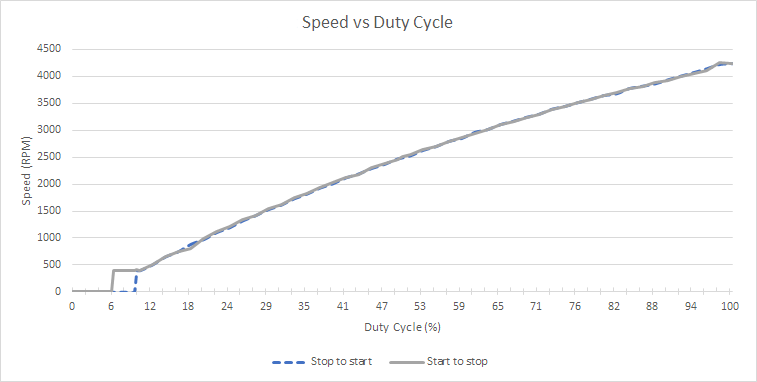
Info
Duty cycle data is converted from Linux PWM
Fan Speed Comparison
Helios4 Temperature Sensors
CPU Thermal Sensor
Armada 388 incorporates a Thermal Management engine for monitoring die temperature. It includes an on-die analog-to-digital thermal sensor, that is used to determine when the maximum specified processor junction temperature has been reached.
Ethernet PHY Thermal Sensor
Helios4's 10/100/1000 BASE-T PHY Tranceiver (Marvell 88E1512 Datasheet) features an internal temperature sensor. The sensor reports the die temperature and is updated approximately once per second.
Board Temp Sensor
Helios4 has a Digital Temperature Sensor with 2‐wire Interface (NCT75 Datasheet), located on bottom side of the board. It is used to read ambient temperature.
PWM Fan Control under Linux
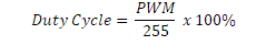
Linux use 8-bit integer to represent duty cycle. PWM value 0 represent 0% duty cycle and PWM value 255 represent 100% duty cycle.
Below graphs are bundled fan speed vs pwm value instead of duty cycle.
Patch requirement
Currently Linux gpio-mvebu driver does not allow more than 1 PWM under the same gpio bank. Helios4 uses 2 PWM under same bank therefore this patch needs to be applied to kernel source to remove the restriction.
Using SYSFS interface
Linux export the fan control mechanism to SYSFS under hwmon class. List of devices can be checked under /sys/class/hwmon
ls -l /sys/class/hwmon/
total 0
lrwxrwxrwx 1 root root 0 Jul 26 07:39 hwmon0 -> ../../devices/platform/soc/soc:internal-regs/f1072004.mdio/mdio_bus/f1072004.mdio-mii/f1072004.mdio-mii:00/hwmon/hwmon0
lrwxrwxrwx 1 root root 0 Jul 26 07:39 hwmon1 -> ../../devices/virtual/thermal/thermal_zone0/hwmon1
lrwxrwxrwx 1 root root 0 Jul 26 07:39 hwmon2 -> ../../devices/platform/soc/soc:internal-regs/f1011000.i2c/i2c-0/0-004c/hwmon/hwmon2
lrwxrwxrwx 1 root root 0 Jul 26 07:39 hwmon3 -> ../../devices/platform/j10-pwm/hwmon/hwmon3
lrwxrwxrwx 1 root root 0 Jul 26 07:39 hwmon4 -> ../../devices/platform/j17-pwm/hwmon/hwmon4
Info
The numbering may different from above example output. It depends on whether the driver built as kernel module or built-in, device initialization order. Take this as consideration when using fancontrol
To identify which hwmon belong to fan, look for j10-pwm and j17-pwm. On above example
hwmon3 -> ../../devices/platform/j10-pwm/hwmon/hwmon3
hwmon4 -> ../../devices/platform/j17-pwm/hwmon/hwmon4
To read current PWM
cat /sys/class/hwmon3/pwm1
cat /sys/class/hwmon4/pwm1
To set PWM
echo NEW_PWM_VALUE > /sys/class/hwmon3/pwm1
echo NEW_PWM_VALUE > /sys/class/hwmon4/pwm1
Fancontrol - automated software based fan speed control
fancontrol is a shell script for use with lm_sensors. It reads its configuration from a file, then calculates fan speeds from temperatures and sets the corresponding PWM outputs to the computed values.
sudo apt-get install fancontrol
fancontrol includes pwmconfig script to create automatically a configuration file but it can not be used for Helios4.
UDEV rules
Since hwmon order can be changed between kernel version or even between reboot, on Armbian we use udev rules as workaround. The rules can be found from here and to be copy to /etc/udev/rules.d/
/dev/fan-j10, /dev/fan-j17, /dev/thermal-cpu, /dev/thermal-board, and /dev/thermal-eth are symlinks generated by the udev rules.
Configuration File
fancontrol uses /etc/fancontrol as configuration file. Below is an example configuration to control fan speed on Helios4.
# Helios4 PWM Fan Control Configuration
# Temp source : /dev/thermal-cpu
INTERVAL=10
FCTEMPS=/dev/fan-j10/pwm1=/dev/thermal-cpu/temp1_input /dev/fan-j17/pwm1=/dev/thermal-cpu/temp1_input
MINTEMP=/dev/fan-j10/pwm1=40 /dev/fan-j17/pwm1=40
MAXTEMP=/dev/fan-j10/pwm1=80 /dev/fan-j17/pwm1=80
MINSTART=/dev/fan-j10/pwm1=20 /dev/fan-j17/pwm1=20
MINSTOP=/dev/fan-j10/pwm1=29 /dev/fan-j17/pwm1=29
MINPWM=20
INTERVAL
This variable defines at which interval in seconds the main loop of fancontrol will be executed.
FCTEMPS
Maps PWM outputs to temperature sensors so fancontrol knows which temperature sensors should be used for calculation of new values for the corresponding PWM outputs.
Fans (fan-j10 & fan-j17) are controlled based on CPU thermal sensor (thermal-cpu) reading.
MINSTART
Sets the minimum speed at which the fan begins spinning. You should use a safe value to be sure it works, even when the fan gets old.
Type-C fan restart at 15, added 5 for safety (in case of aging fan) give us 20. The value does not affect Type-A fan.
MINSTOP
The minimum speed at which the fan still spins. Use a safe value here, too.
Type-C fan stopped at 24, added 5 for safety (in case of aging fan) give us 29. The value does not affect Type-A fan.
Following settings can be adjusted by user to tweak further.
MINTEMP
The temperature below which the fan gets switched to minimum speed.
Fans (fan-j10 & fan-j17) runs in minimum speed if the CPU temperature below 40 degree C.
MAXTEMP
The temperature over which the fan gets switched to maximum speed.
Fans (fan-j10 & fan-j17) runs in maximum speed if the CPU temperature above 80 degree C.
MINPWM
The PWM value to use when the temperature is below MINTEMP. Typically, this will be either 0 if it is OK for the fan to plain stop, or the same value as MINSTOP if you don't want the fan to ever stop. If this value isn't defined, it defaults to 0 (stopped fan).
Set minimum PWM value to 0. On Type-C fan, it would stopped the fan while on Type-A fan it would run in minimal speed.
Note
The Helios4 fancontrol configuration file can be found here.
Thermal Zone on Device Tree
As an alternative to userspace tool like fancontrol, Linux Kernel provides Thermal Framework to do thermal management.
Below is an example of device tree nodes that can be added to Helios4 device tree to make use of Linux Thermal Framework.
Note
Currently armada_thermal driver (CPU Thermal Sensor) does not support thermal-zone binding in device tree, therefore it can not be used as thermal-sensor yet.
/ {
   ...

    fan1: j10-pwm {
        compatible = "pwm-fan";
        pwms = <&gpio1 9 40000>;    /* Target freq:25 kHz */
        cooling-min-state = <0>;
        cooling-max-state = <3>;
        #cooling-cells = <2>;
        cooling-levels = <0 25 128 255>;
    };

    fan2: j17-pwm {
        compatible = "pwm-fan";
        pwms = <&gpio1 23 40000>;   /* Target freq:25 kHz */
        cooling-min-state = <0>;
        cooling-max-state = <3>;
        #cooling-cells = <2>;
        cooling-levels = <0 25 128 255>;
    };

    thermal-zones {
        microsom_thermal: microsom-thermal {
            thermal-sensors = <&thermal>;
            polling-delay-passive = <250>; /* milliseconds */
            polling-delay = <500>; /* milliseconds */
            trips {
                cpu_active: cpu_active {
                    /* millicelsius */
                    temperature = <40000>;
                    hysteresis = <2000>;
                    type = "active";
                };

                cpu_alert: cpu_alert {
                    /* millicelsius */
                    temperature = <80000>;
                    hysteresis = <2000>;
                    type = "hot";
                };

                cpu_crit: cpu-crit {
                    /* millicelsius */
                    temperature = <115000>;
                    hysteresis = <5000>;
                    type = "critical";
                };
            };
        };

        board_thermal: board-thermal {
            thermal-sensors = <&temp_sensor>;
            polling-delay-passive = <0>; /* milliseconds */
            polling-delay = <1500>; /* milliseconds */
            trips {
                board_active: board-active {
                    /* millicelsius */
                    temperature = <40000>;
                    hysteresis = <2000>;
                    type = "active";
                };

                board_alert: board-alert {
                    /* millicelsius */
                    temperature = <60000>;
                    hysteresis = <2000>;
                    type = "hot";
                };

                board_critical: board-critical {
                    /* millicelsius */
                    temperature = <70000>;
                    hysteresis = <2000>;
                    type = "critical";
                };
            };

            cooling-maps {
                map0 {
                    trip = <&board_active>;
                    cooling-device = <&fan1 THERMAL_NO_LIMIT 2>,
                             <&fan2 THERMAL_NO_LIMIT 2>;
                };
                map1 {
                    trip = <&board_alert>;
                    cooling-device = <&fan1 2 THERMAL_NO_LIMIT>,
                             <&fan2 2 THERMAL_NO_LIMIT>;
                };
            };
        };
    };
    ...
};

&temp_sensor {
    #thermal-sensor-cells = <0>;
};
References
4-Wire Pulse Width Modulation (PWM) Controlled Fans Specification rev. 1.3
Linux Thermal Framework Device Tree descriptor