PWM Fan
PWM Introduction
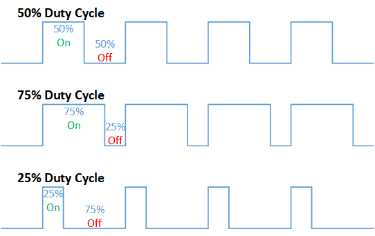
PWM, or pulse width modulation is a technique which allows us to adjust the average value of the voltage that’s going to the electronic device by varying duty cycle of the power at a fast rate.
The term duty cycle describes the proportion of 'on' time to the regular interval or 'period' of time; a low duty cycle corresponds to low power, because the power is off for most of the time. Duty cycle is expressed in percent, 100% being fully on. When a digital signal is on half of the time and off the other half of the time, the digital signal has a duty cycle of 50% and resembles a "square" wave. When a digital signal spends more time in the on state than the off state, it has a duty cycle of >50%. When a digital signal spends more time in the off state than the on state, it has a duty cycle of <50%. Here is a pictorial that illustrates these three scenarios:
PWM Fan Implementation
Type-A
Type-B
Type-C
PWM Fan Schematic
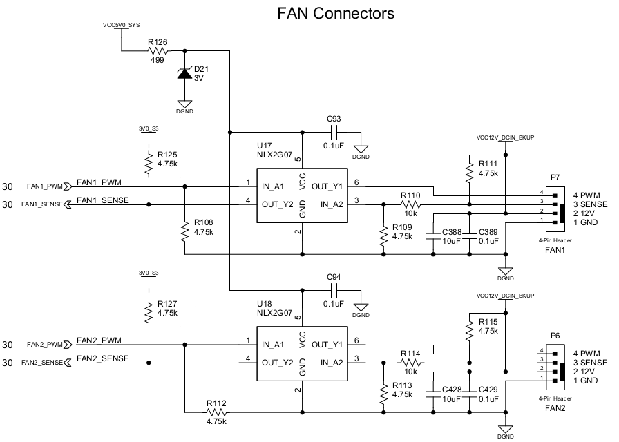
Remarks
| Description | Header P7 | Header P6 | Remarks |
|---|---|---|---|
| PWM pin | PWM0 | PWM1 | 5V tolerant |
| SENSE pin | GPIO4_C5 | GPIO4_C7 | no kernel module/userspace apps that make use of this pin yet |
| PWM Frequency | 25 kHz | 25 kHz | defined in device tree |
PWM Fan Connector

Connector Pinout
| Pin | Function | Wire Color |
|---|---|---|
| 1 | GND | Black |
| 2 | 12V | Red |
| 3 | Sense | Yellow |
| 4 | Control | Blue |
Stock Fan
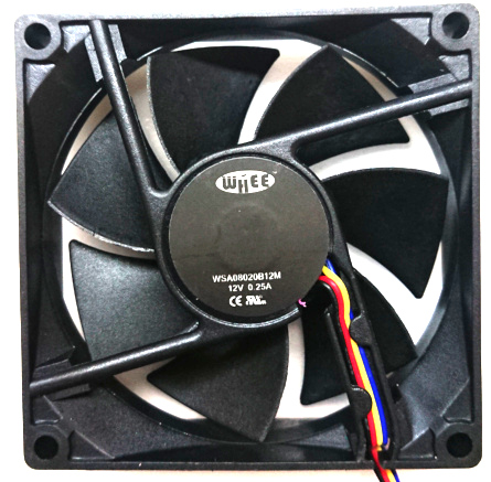
Fan Specifications
| Parameter | Value | Unit | Remarks |
|---|---|---|---|
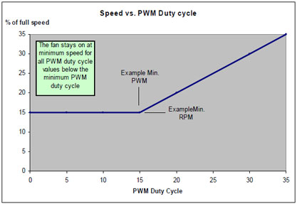
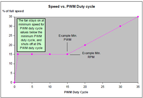
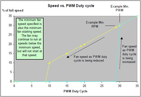
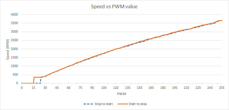
| Maximum Speed | 3600 | RPM | @ duty cycle 98% |
| Minimum Speed | 350 | RPM | @ duty cycle 10% |
| Shut off | Yes | duty cycle < 6.5% and restart @ duty cycle > 9.5% | |
| Implementation | Type-C |
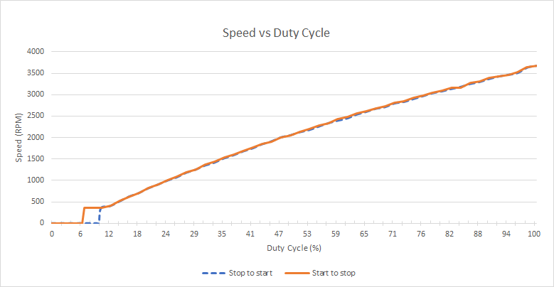
Info
Duty cycle data is converted from Linux PWM
Helios64 Temperature Sensors
SoC Temperature Sensor
RK3399 has internal temperature sensor (TS-ADC) for monitoring die temperature. The system has two Temperature Sensors, channel 0 is for CPU, channel 1 is for GPU.
The sensor has -40~125°C temperature range and 5°C temperature resolution.
Board Temp Sensor
Helios64 has a Digital Temperature Sensor with 2‐wire Interface (NCT75 Datasheet), located on top side of the board near RTC battery. It is used to read ambient temperature.
PWM Fan Control under Linux
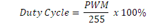
Linux uses 8-bit integer to represent duty cycle. PWM value 0 represent 0% duty cycle and PWM value 255 represent 100% duty cycle.
Below graphs is stock fan speed vs pwm value instead of duty cycle.
Using SYSFS interface
Linux exports the fan control mechanism to SYSFS under hwmon class. List of devices can be checked under _/sys/class/hwmon*
ls -l /sys/class/hwmon/
total 0
lrwxrwxrwx 1 root root 0 Oct 16 08:38 hwmon0 -> ../../devices/virtual/thermal/thermal_zone0/hwmon0
lrwxrwxrwx 1 root root 0 Oct 16 08:38 hwmon1 -> ../../devices/virtual/thermal/thermal_zone1/hwmon1
lrwxrwxrwx 1 root root 0 Oct 16 08:38 hwmon2 -> ../../devices/platform/ff120000.i2c/i2c-2/2-004c/hwmon/hwmon2
lrwxrwxrwx 1 root root 0 Oct 16 09:29 hwmon3 -> ../../devices/platform/gpio-charger/power_supply/gpio-charger/hwmon3
lrwxrwxrwx 1 root root 0 Oct 16 09:29 hwmon4 -> ../../devices/platform/p7-fan/hwmon/hwmon4
lrwxrwxrwx 1 root root 0 Oct 16 09:29 hwmon5 -> ../../devices/platform/p6-fan/hwmon/hwmon5
lrwxrwxrwx 1 root root 0 Oct 16 09:29 hwmon6 -> ../../devices/platform/ff3d0000.i2c/i2c-4/4-0022/power_supply/tcpm-source-psy-4-0022/hwmon6
Info
The numbering may differ from above example output. It depends on whether the driver built as kernel module or built-in and device initialization order. Take this as consideration when using fancontrol
To identify which hwmon belong to fan, look for p6-fan and p7-fan. On above example
hwmon4 -> ../../devices/platform/p7-fan/hwmon/hwmon4
hwmon5 -> ../../devices/platform/p6-fan/hwmon/hwmon5
To read current PWM
cat /sys/class/hwmon4/pwm1
cat /sys/class/hwmon5/pwm1
To set PWM
echo NEW_PWM_VALUE > /sys/class/hwmon4/pwm1
echo NEW_PWM_VALUE > /sys/class/hwmon5/pwm1
( NEW_PWM_VALUE takes value between 0 and 255 )
Fancontrol Utility
fancontrol software provides automated fan speed control. It is a shell script for use with lm_sensors. It reads its configuration from a file, then calculates fan speeds from temperatures and sets the corresponding PWM outputs to the computed values.
sudo apt-get install fancontrol
fancontrol includes pwmconfig script to create automatically a configuration file but it cannot be used for Helios64.
UDEV rules
Since hwmon order can change between kernel version or even between reboot, on Armbian we use udev rules as workaround. The rules can be found here (mainline) or here (legacy kernel 4.4) and need to be copied to /etc/udev/rules.d/
/dev/fan-p6, /dev/fan-p7, /dev/thermal-cpu and /dev/thermal-board are symlinks generated by the udev rules.
Configuration File
fancontrol uses /etc/fancontrol as configuration file. Below is an example configuration to control fan speed on Helios64.
# Helios64 PWM Fan Control Configuration
# Temp source : /dev/thermal-cpu
INTERVAL=10
FCTEMPS=/dev/fan-p6/pwm1=/dev/thermal-cpu/temp1_input /dev/fan-p7/pwm1=/dev/thermal-cpu/temp1_input
MINTEMP=/dev/fan-p6/pwm1=40 /dev/fan-p7/pwm1=40
MAXTEMP=/dev/fan-p6/pwm1=80 /dev/fan-p7/pwm1=80
MINSTART=/dev/fan-p6/pwm1=20 /dev/fan-p7/pwm1=20
MINSTOP=/dev/fan-p6/pwm1=29 /dev/fan-p7/pwm1=29
MINPWM=20
INTERVAL
This variable defines at which interval in seconds the main loop of fancontrol will be executed.
FCTEMPS
Maps PWM outputs to temperature sensors so fancontrol knows which temperature sensors should be used for calculation of new values for the corresponding PWM outputs.
Fans (fan-p6 & fan-p7) are controlled based on CPU thermal sensor (thermal-cpu) reading.
MINSTART
Sets the minimum speed at which the fan begins spinning. You should use a safe value to be sure it works, even when the fan gets old.
Stock fan restart at 15, added 5 for safety (in case of aging fan) give us 20.
MINSTOP
The minimum speed at which the fan still spins. Use a safe value here, too.
Stock fan stopped at 24, added 5 for safety (in case of aging fan) give us 29.
Following settings can be adjusted by user to tweak further.
MINTEMP
The temperature below which the fan gets switched to minimum speed.
Fans (fan-p6 & fan-p7) runs in minimum speed if the CPU temperature below 40 degree C.
MAXTEMP
The temperature over which the fan gets switched to maximum speed.
Fans (fan-p6 & fan-p7) runs in maximum speed if the CPU temperature above 80 degree C.
MINPWM
The PWM value to use when the temperature is below MINTEMP. Typically, this will be either 0 if it is OK for the fan to plain stop, or the same value as MINSTOP if you don't want the fan to ever stop. If this value isn't defined, it defaults to 0 (stopped fan).
Note
The Helios64 fancontrol configuration file can be found here.