Helios64 Enclosure Kit
Kit Content
The Helios64 Enclosure Kit contains the following :
- Aluminum Enclosure (1x)
- HDD 3.5″ Plastic Tray (5x)
- HDD Backplane Harness (1x)
- Control Front Panel (1x)
- Sticker Kit (1x)
- Screw Assembly (1x)
- PWM Fan 80mm (w/ Grid) (2x)
- Foam Pads (6x)
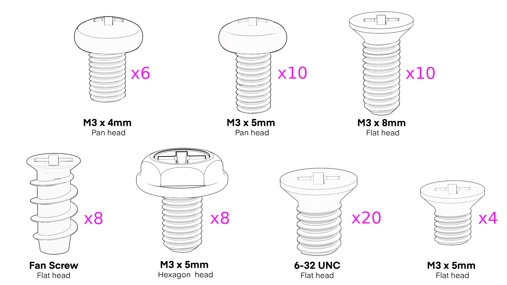
Screw List
Prerequisite
The Enclosure Kit has been specially designed for the Helios64 board. The following items, not provided in the kit, will be necessary to complete the assembly and the setup.
1/ Helios64 Board (with Heatsink)

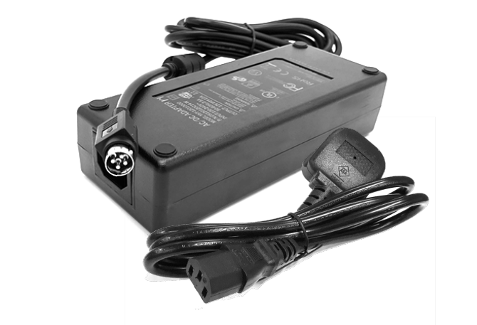
2/ Power Adapter 12V / 10A (with AC cable)
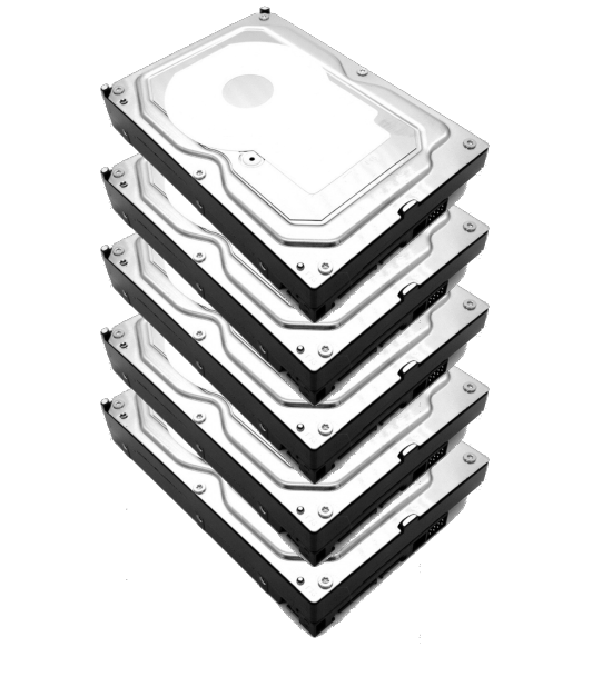
3/ 3.5" HDD - SATA 3.0 Drive (1 to 5 pieces)
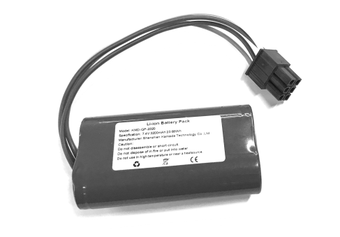
4/ Helios64 UPS Battery (Optional)
5/ Type-C to Type-A USB3.0 Cable
6/ Ethernet Cable Cat5E or Cat6
Tools Required:
- Phillips #2 Screwdriver
- Cutting Pliers or Scissors
- Some patience...
Assembly Instruction
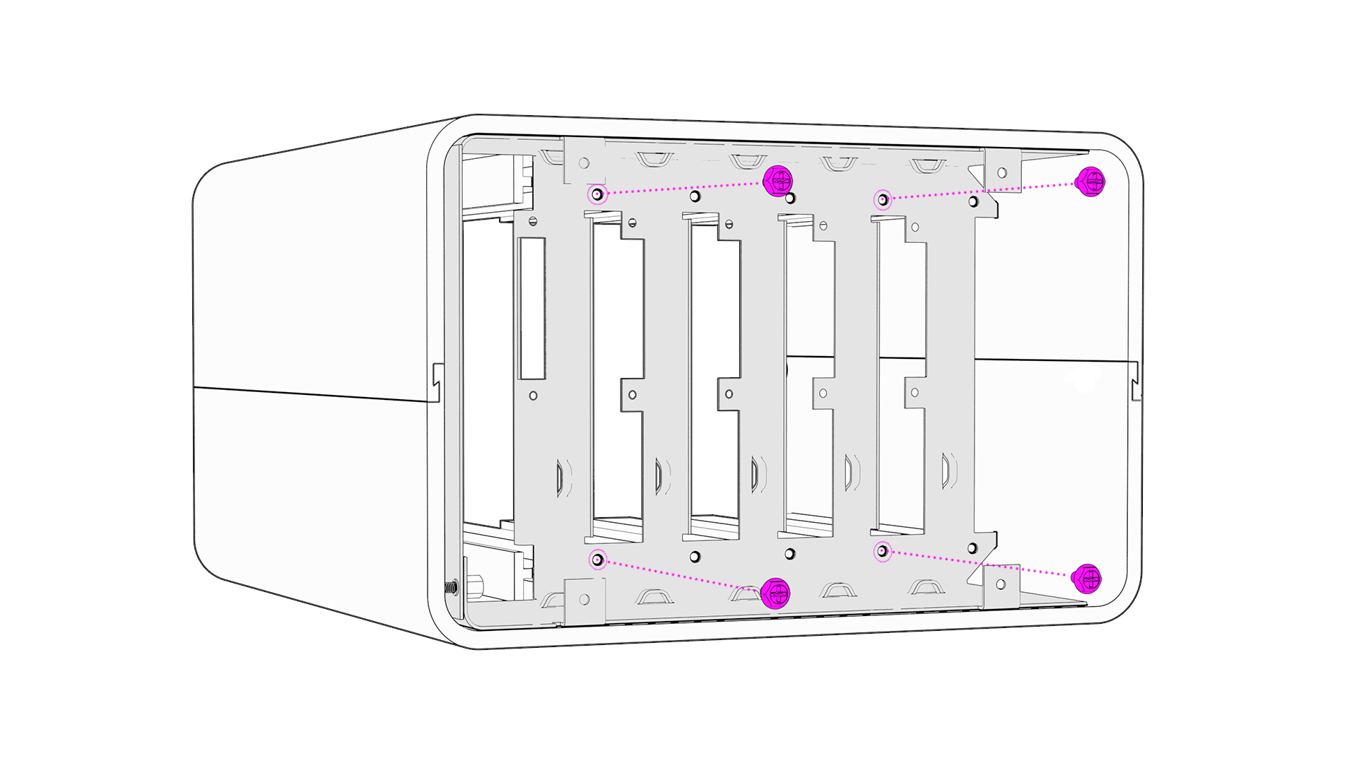
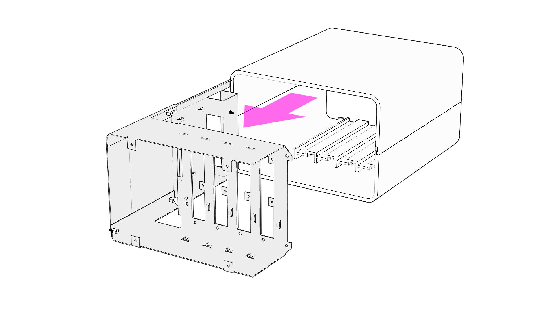
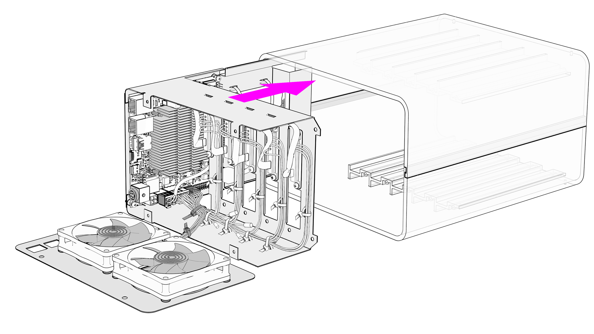
STEP 1 - Disassemble Backplane
Unscrew the 4x Screw (M3 x 5mm Hexagon Head).
Pull out the Internal Backplane.
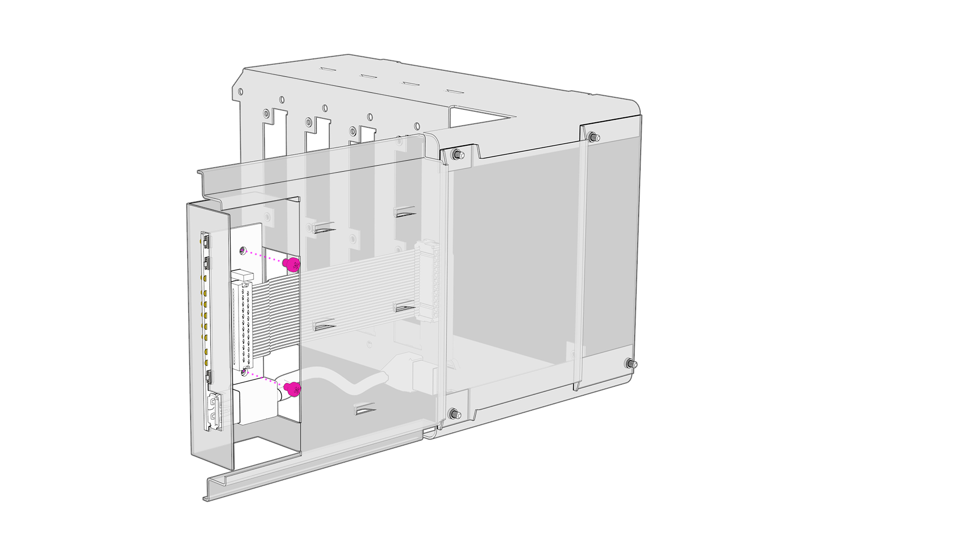
STEP 2 - Install Front Panel
Insert the Front Panel.
Position the Front Panel on top of the 2x standoffs.
Secure the Front Panel with 2x screws (M3 x 4mm Pan Head).
Install the Front Panel Sticker.
Important
Position the sticker to be perfectly aligned and flushed with the top, bottom and right edges of the metal plate.
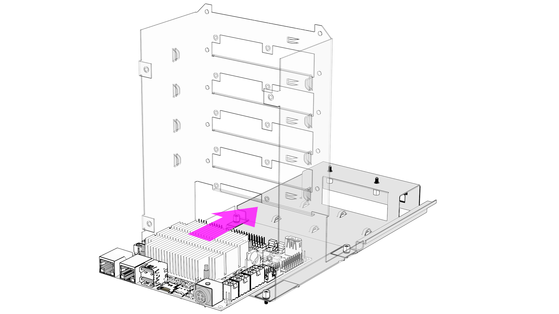
STEP 3 - Install Helios64 Board
Note
If you want to install an M.2 SSD, it is recommended to do it now. Please refer to the following page.
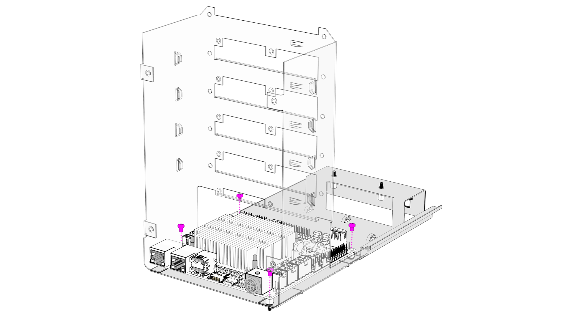
Position the Helios64 board on top of the 4x standoffs.
Secure Heliso64 board with 4x screws (M3 x 4mm Pan Head).
STEP 4 - Install UPS Battery (Optional)
Insert the 2x long cable ties through the anchor slots.
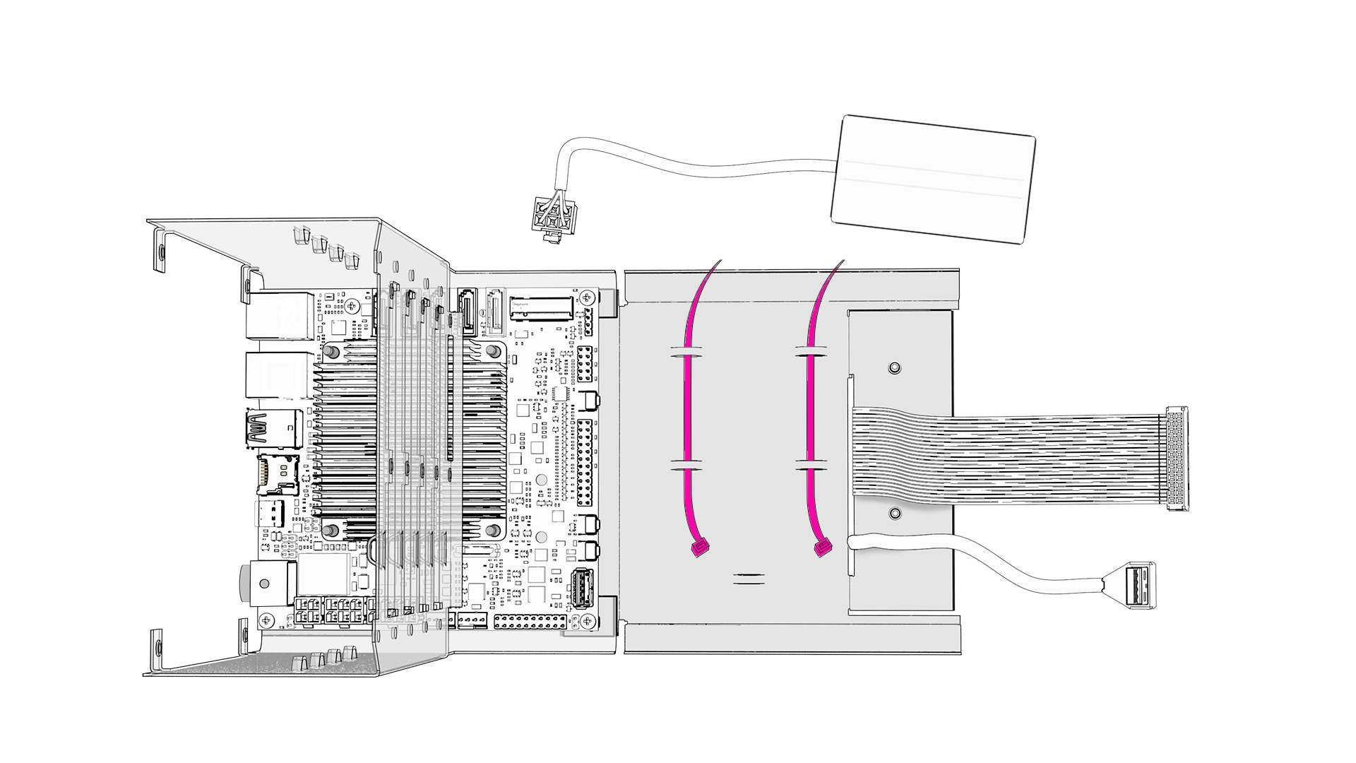
Position battery and secure it with the cable ties (cut the cable zip tie excess).
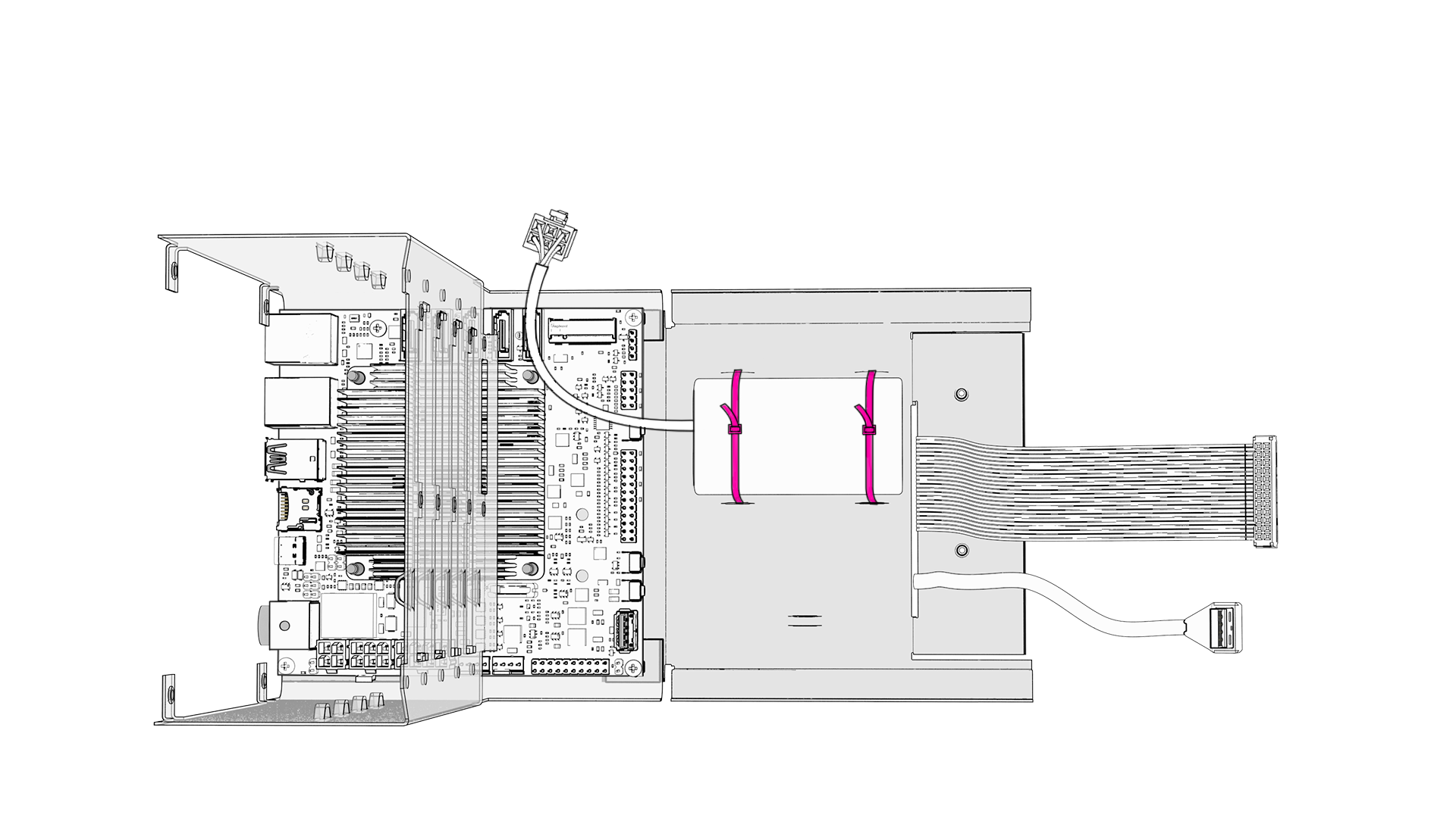
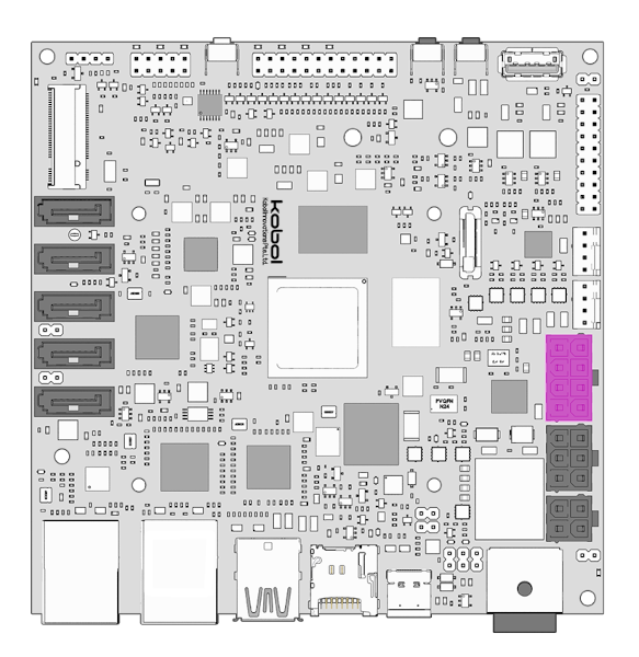
Connect the 6-Pin Molex connector to Helios64 board.
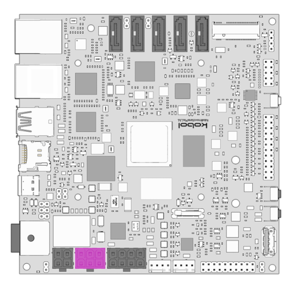
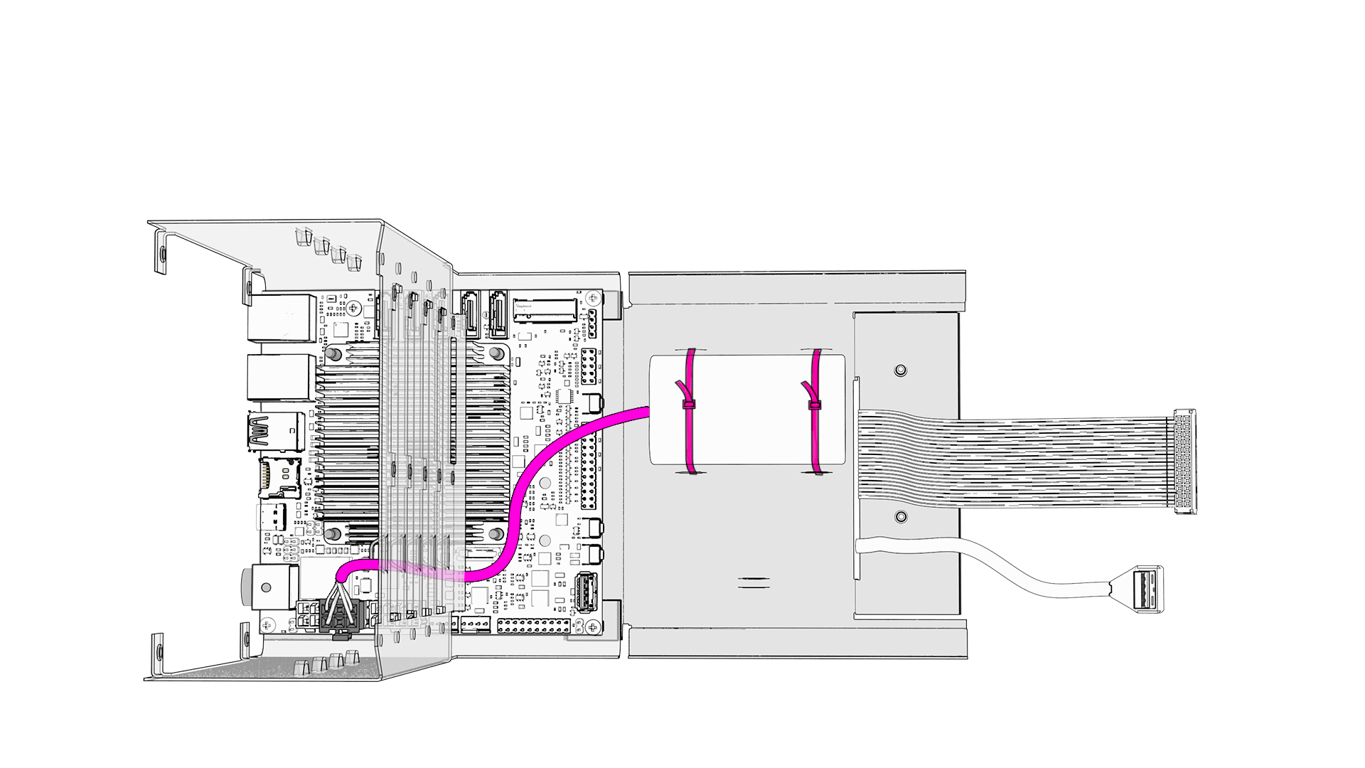
Note
Run the battery cable according to the drawing above.
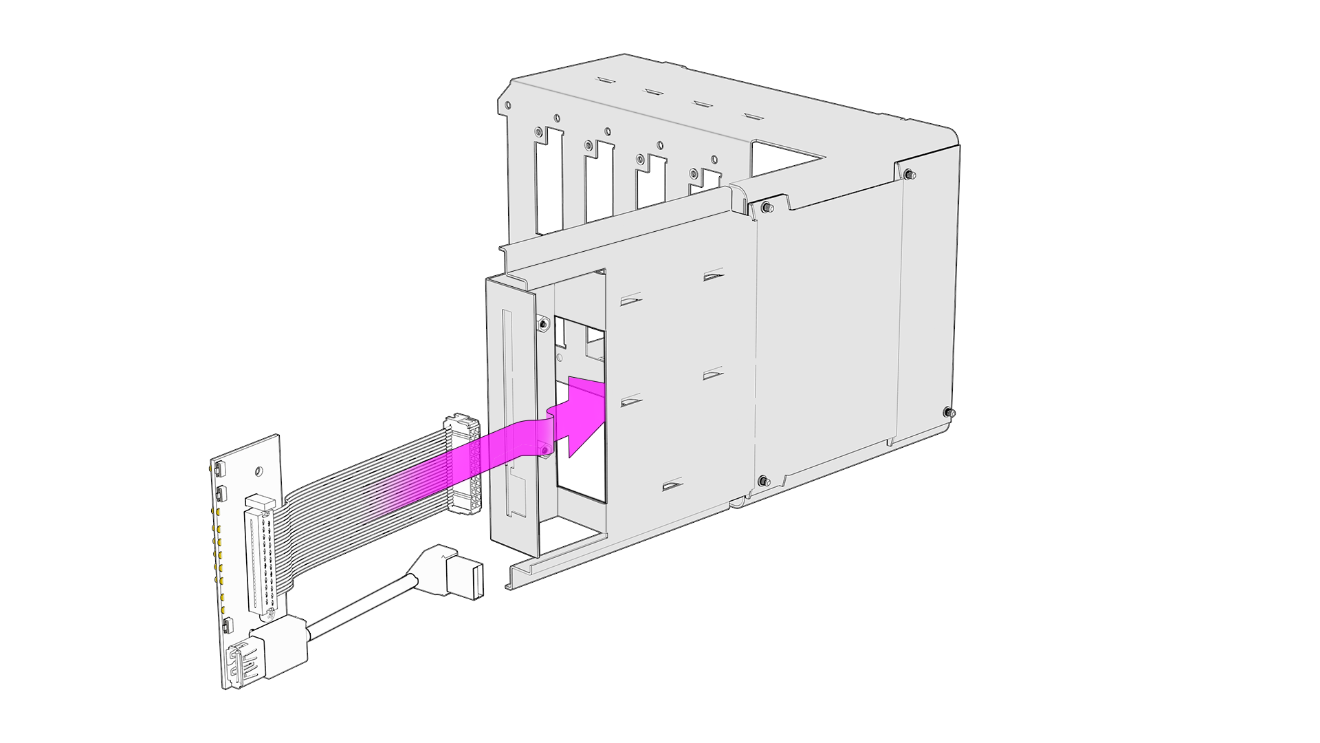
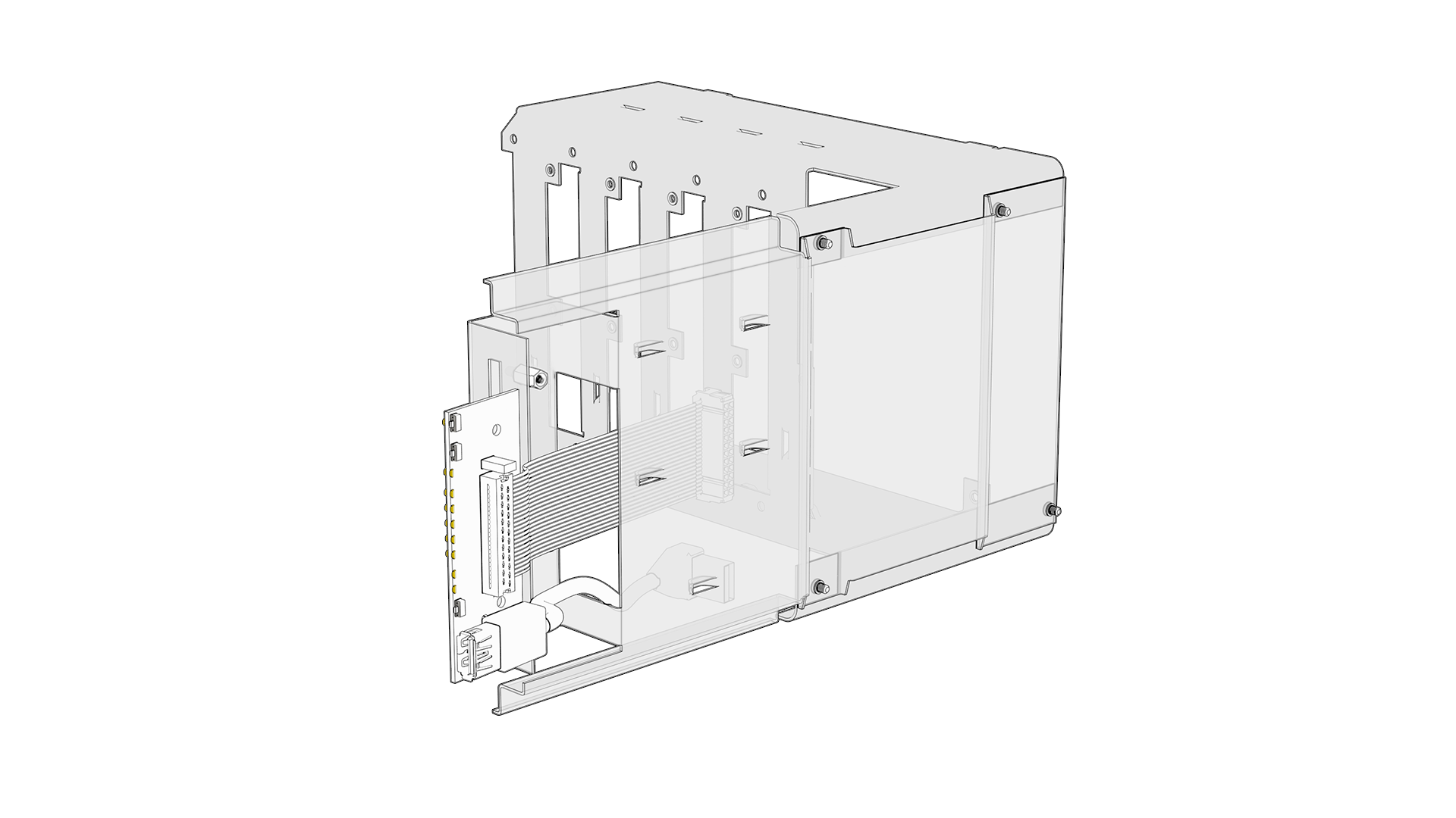
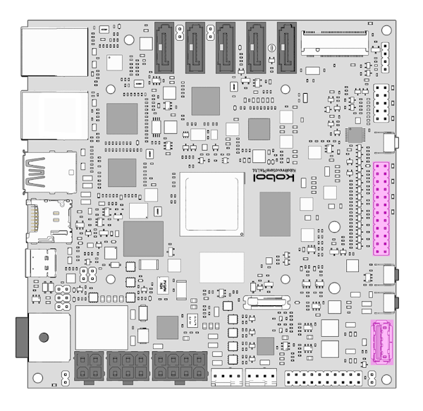
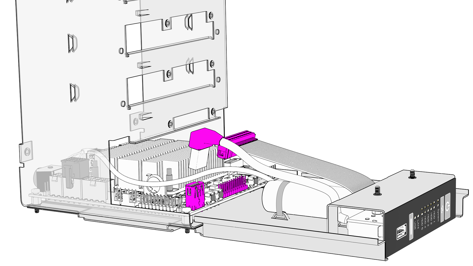
STEP 5 - Connect Front Panel
Connect the Front Panel USB connector to the Helios64 board, then do the same for the IDC connector.
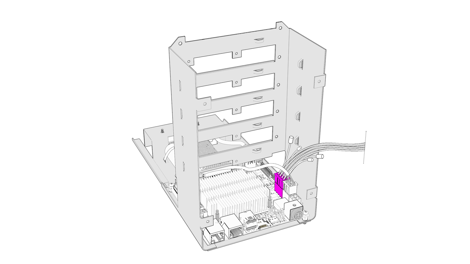
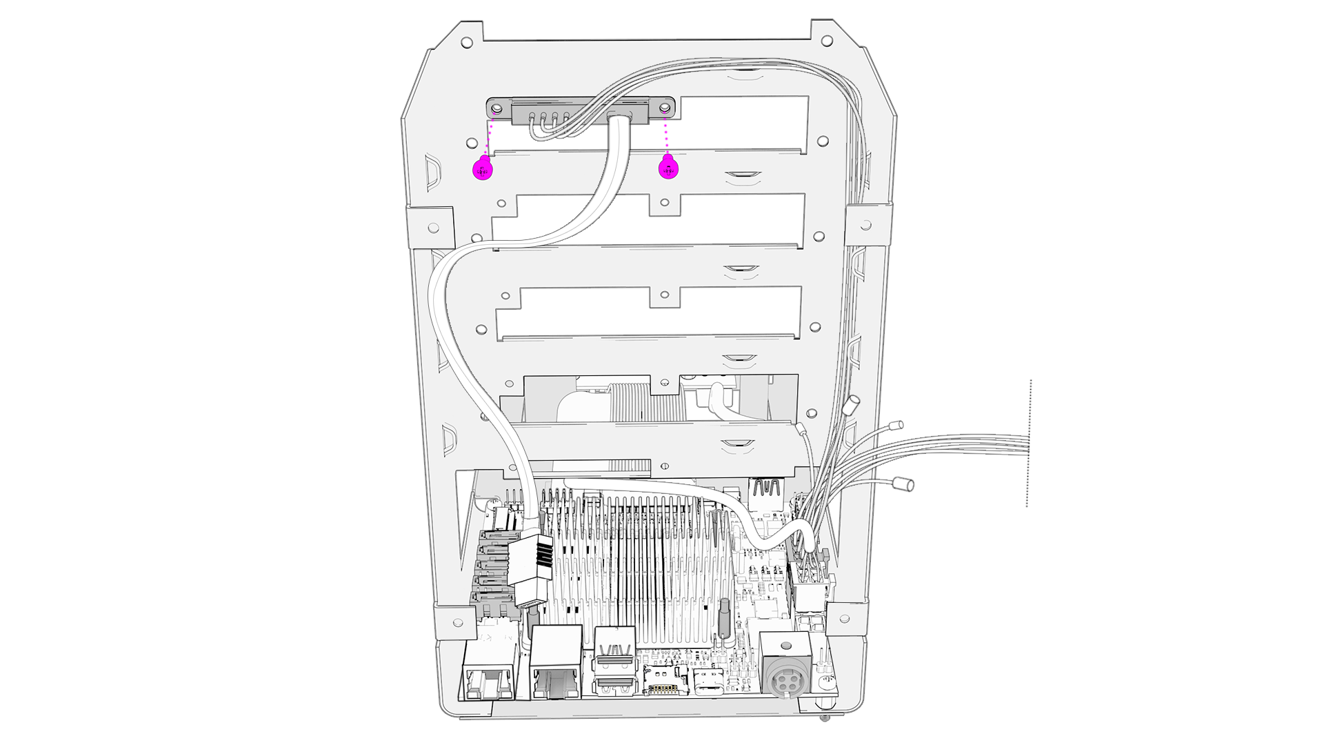
STEP 6 - Install HDD Harness
Prepare the harness by sorting / untangle the wires to identify each connector based on their cable length.
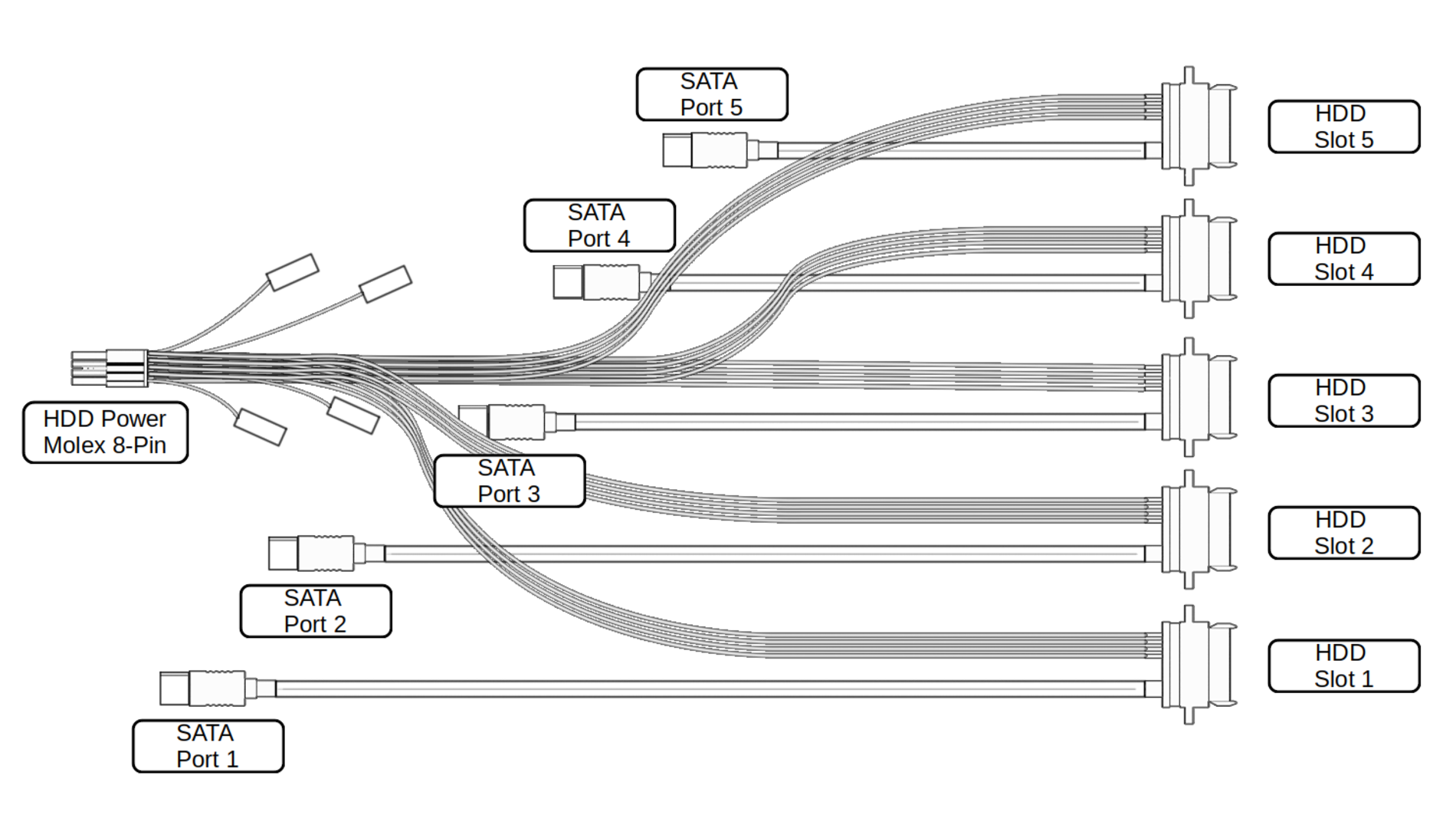
Note
The longest cable is for HDD Slot 1. The second longest is for HDD Slot 2 and so on...
Connect the 8-Pin Molex connector to Helios64 board.
Install HDD Slot 1 connector with 2x screws (M3 x 5mm Pan Head).
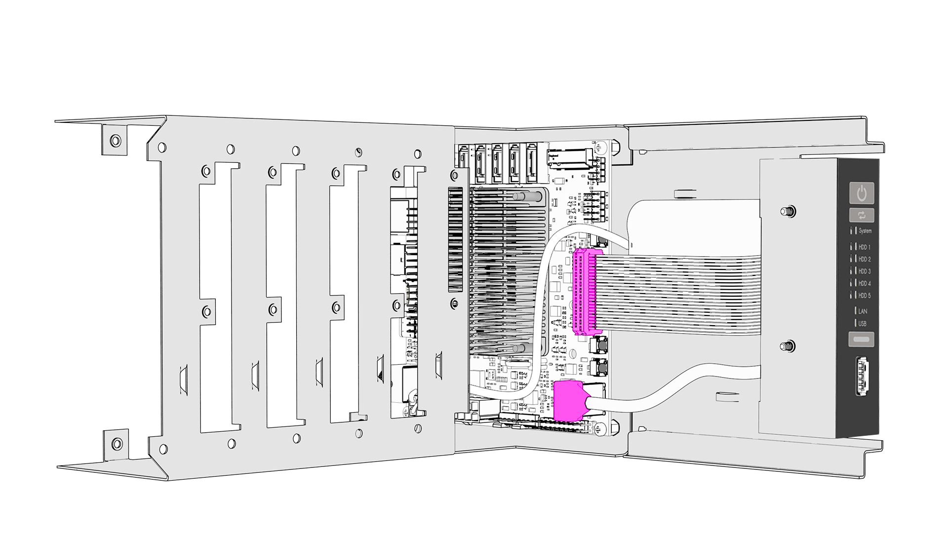
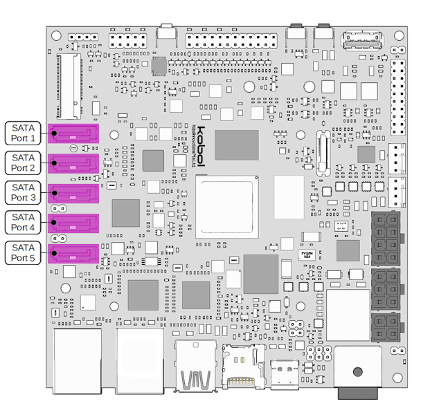
Important
- Pay attention to HDD Slot connector orientation. The 4 power wires are supposed to be on the left, while the SATA cable is on the right. Power wires and SATA cable will cross each others which is expected. If you install the HDD Slot connector wrongly, then you won't be able to insert the HDD and might damage the connector.
- The HDD Slot connectors are made of soft plastic. Don't screw too tight, you don't want the screws to deform the plastic mounting hole.
Connect SATA cable to Helios64 board SATA Port 1. Then Secure the SATA cable with a cable tie like on the drawing below (cut the cable zip tie excess).

Secure the power wires with 2x cable ties like on the drawing below (cut the cable zip tie excess).
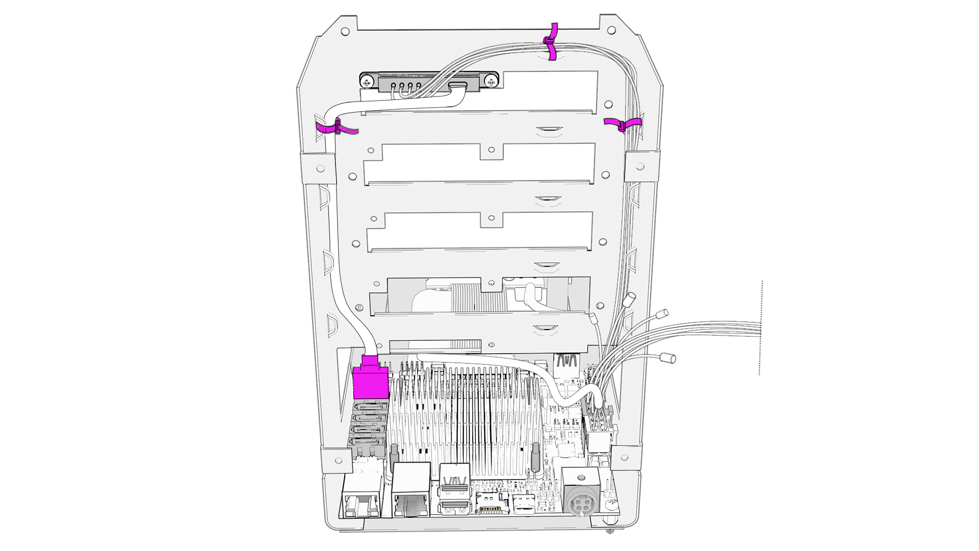
Repeat the same actions for HDD Slot 2 connector and connect its SATA cable to Helios64 board SATA Port 2.

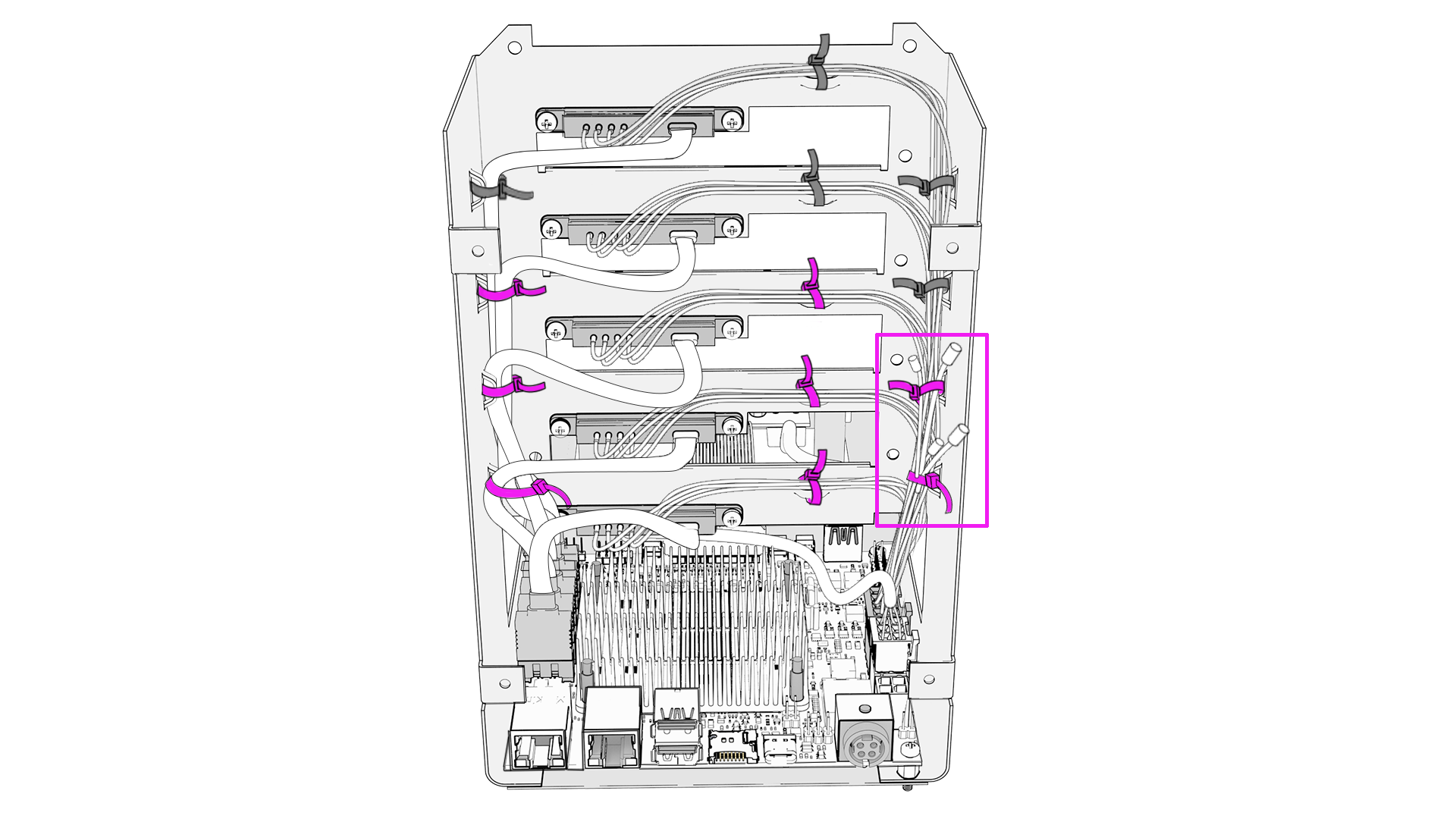
Repeat the same actions for HDD Slot 3, 4 and 5 connectors. The completed harness installation should look like the drawing below.
Important
The harness includes 4x capacitors (little black cylinders) which their own attached wires. While install HDD Slot 3 and 4 connectors, you need to secure these capacitors together with the HDD power wires as shown in the drawing below.
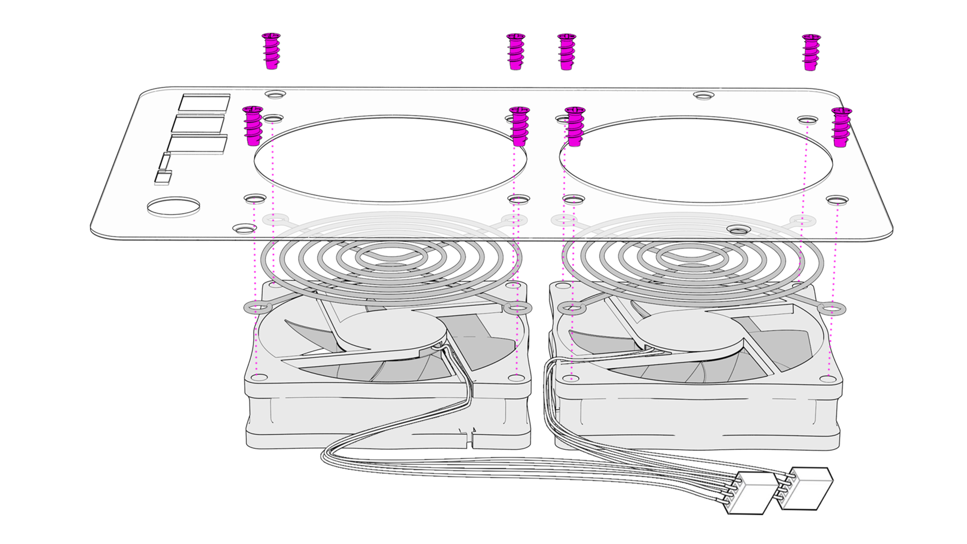
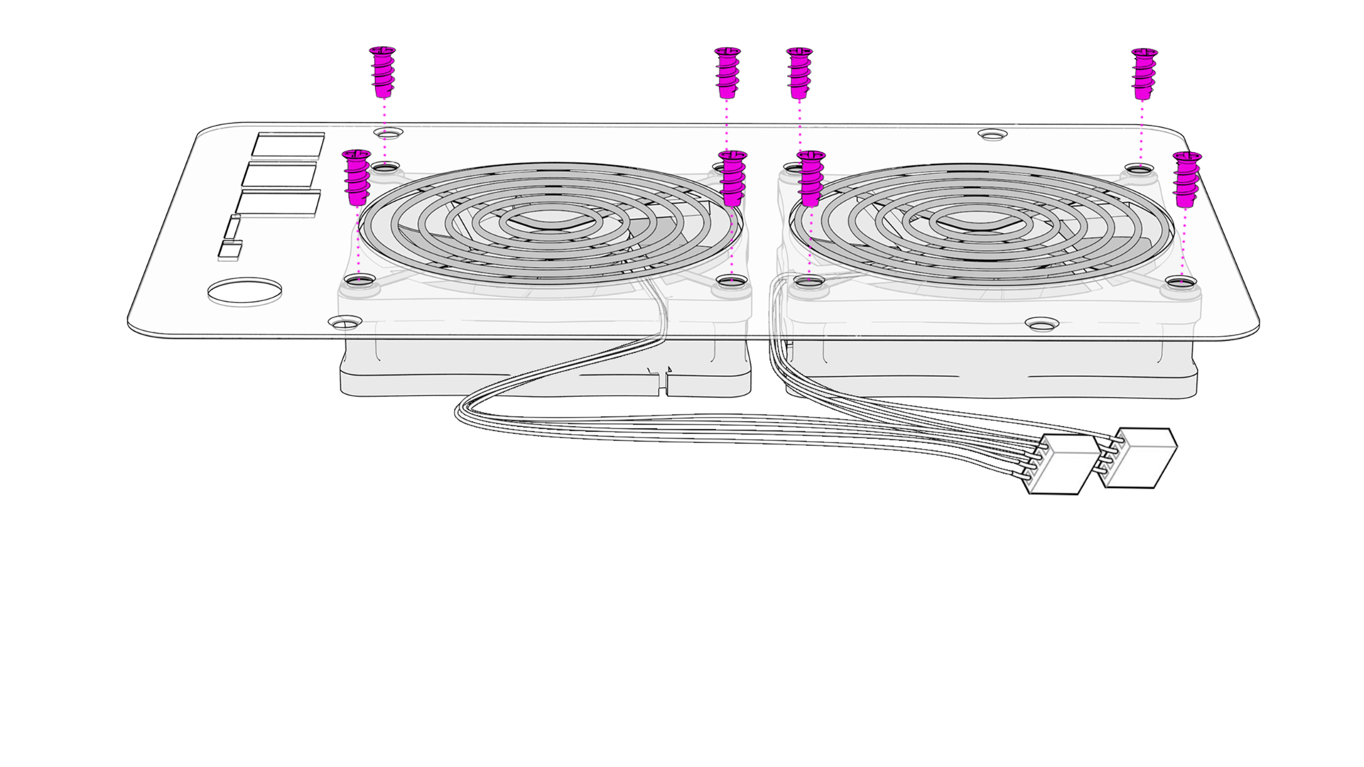
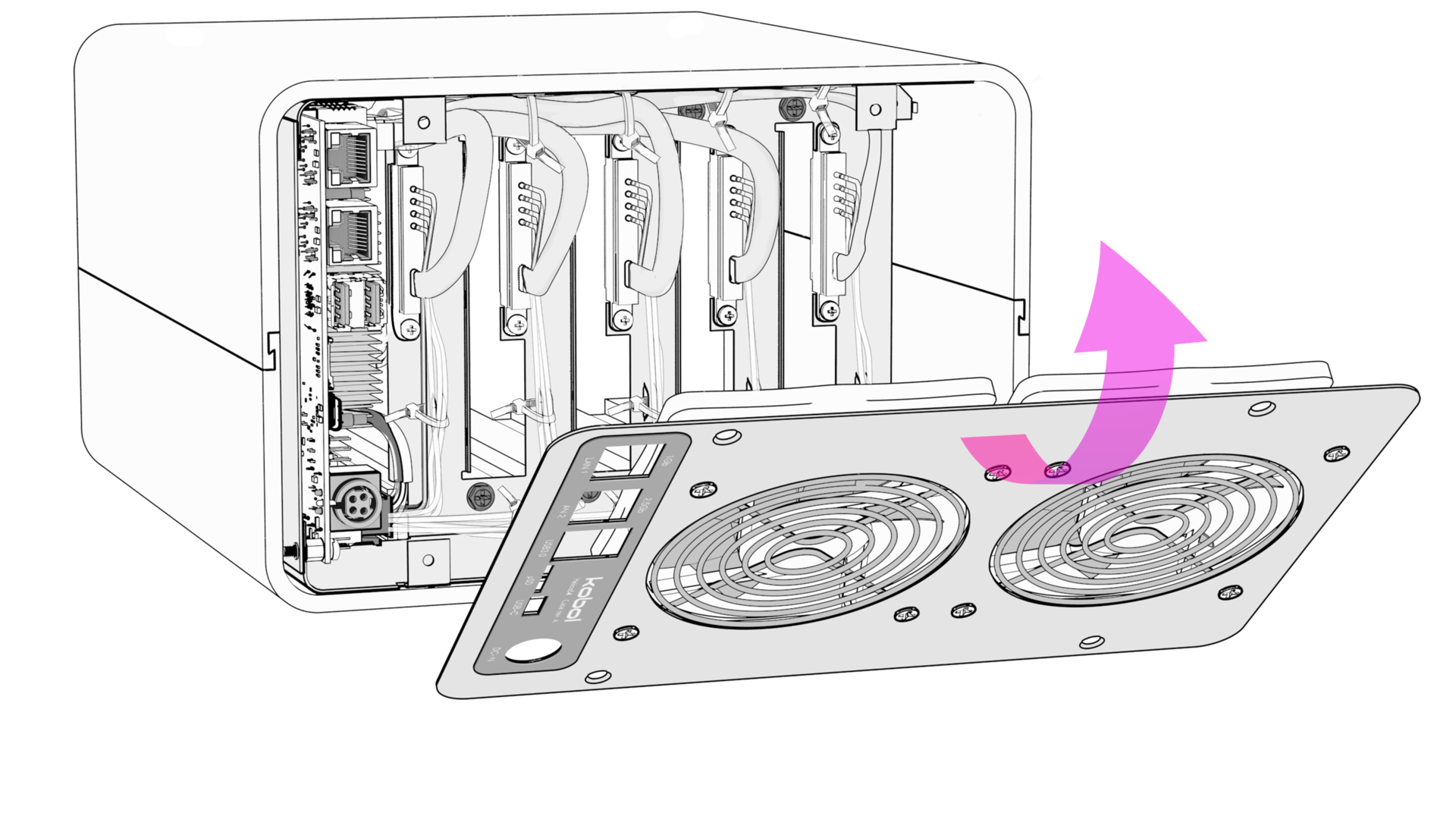
STEP 7 - Install Back Panel
Install the 2x Fans with their grids to back panel with 8x screws (PC Fan Screw)
Important
Pay attention to the orientation off all items (back panel, fans and their grid) in the drawing below. Wrong assembly will impact air flow direction.
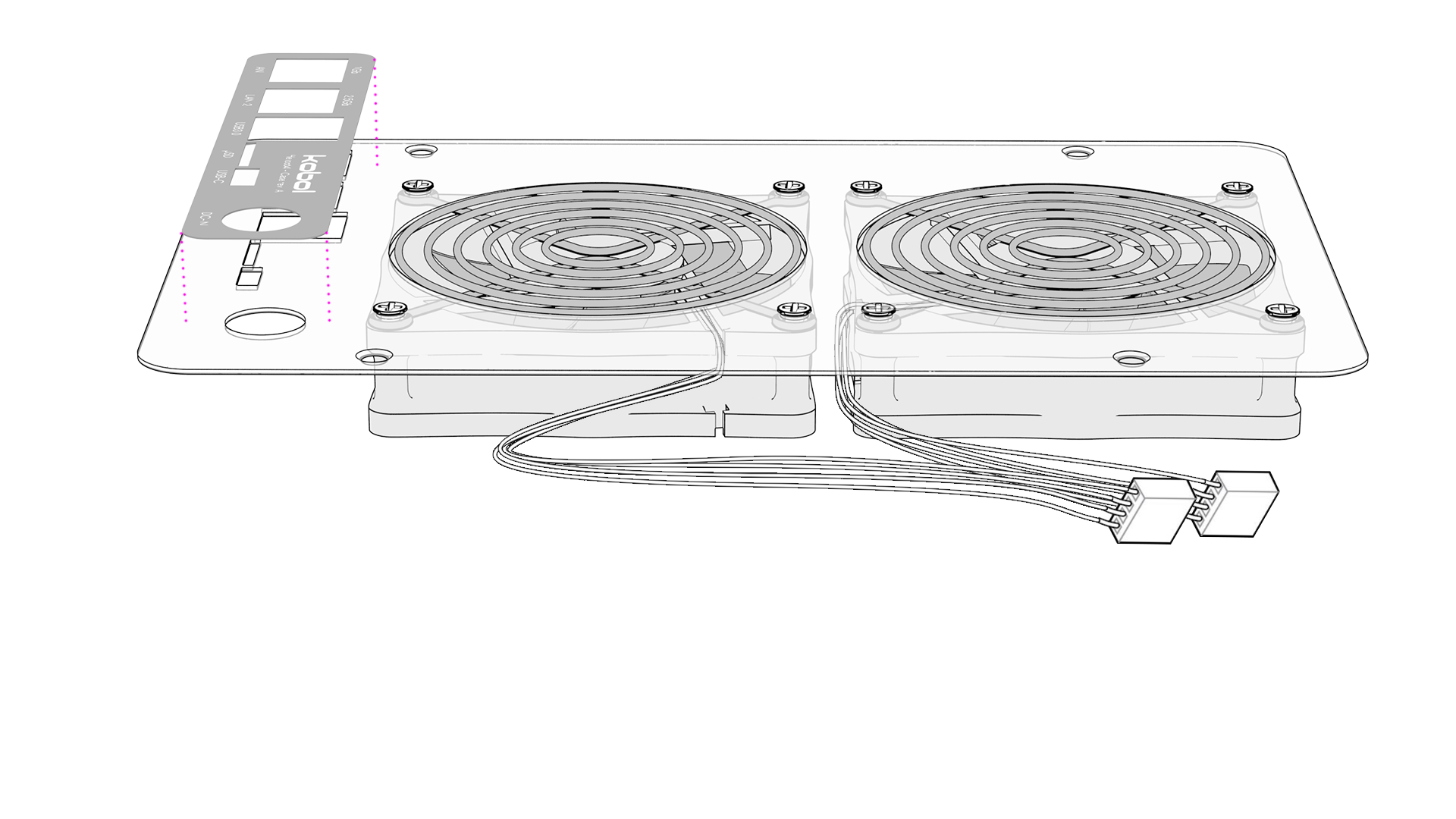
Install the Back Panel Sticker.
Important
Position the sticker to be perfectly aligned with the port holes.
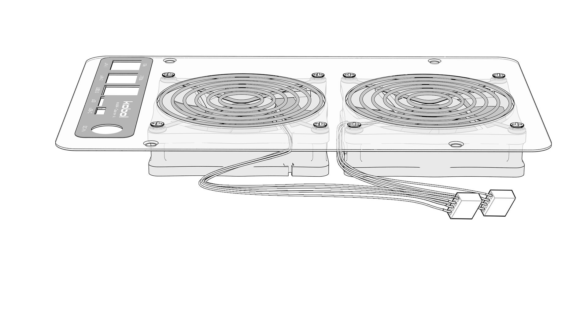
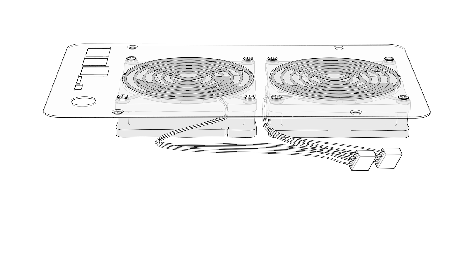
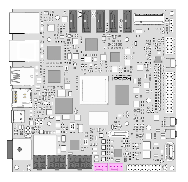
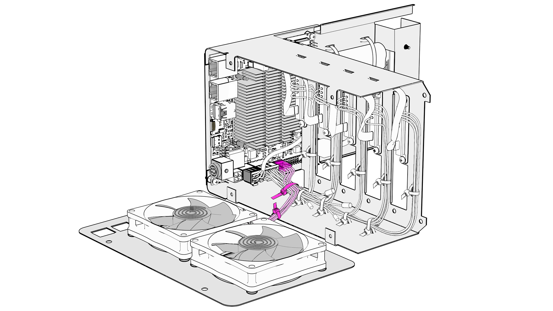
Connect Fan cables to Helios64 board Fan connectors.
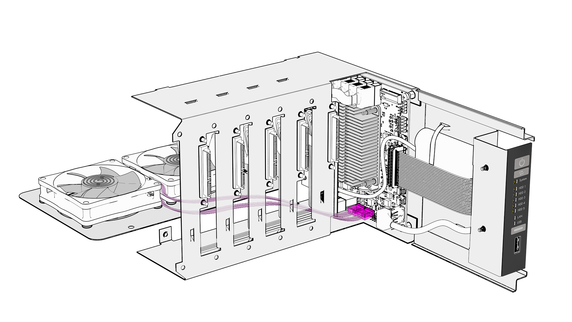
Use cable ties like on the drawing below (cut the cable zip tie excess).
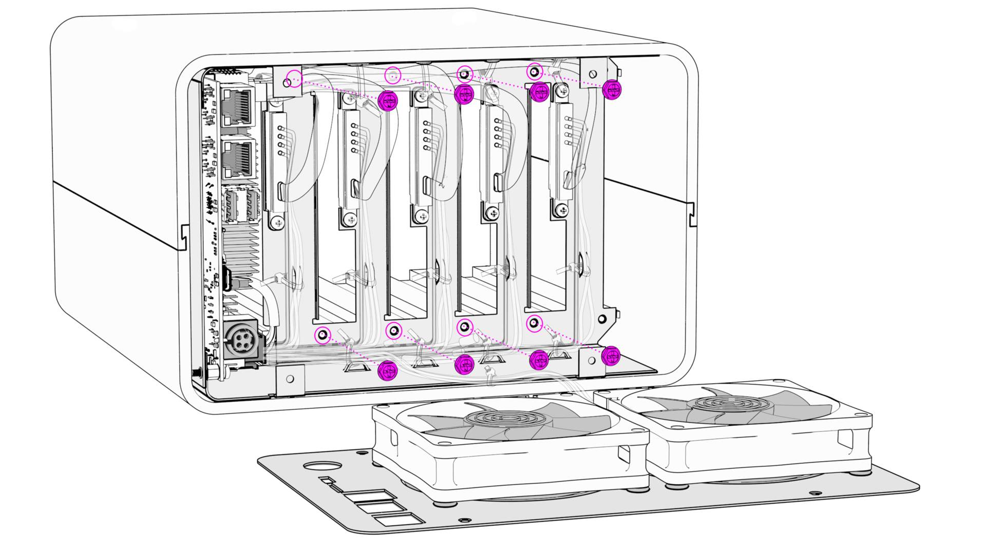
STEP 8 - Reassemble Enclosure
Insert Backplane inside Aluminum enclosure.
Secure Backplane to the enclosure with 8x screws (M3 x 5mm Hexagon Head).
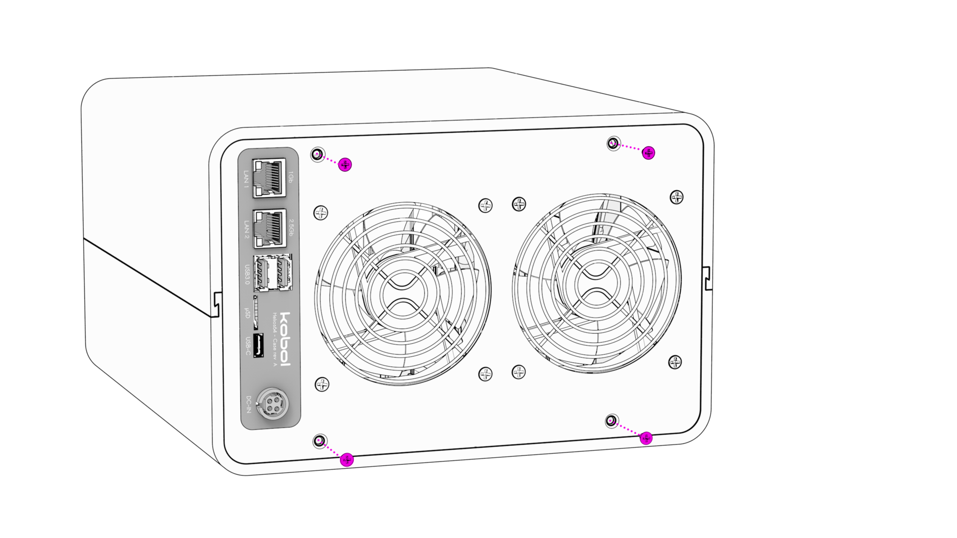
Insert Back Panel
Important
Insure you are well aligned with Helios64 Board ports when inserting the Back Panel.
Secure Back Panel with 4x screws (M3 x 5mm Flat Head).
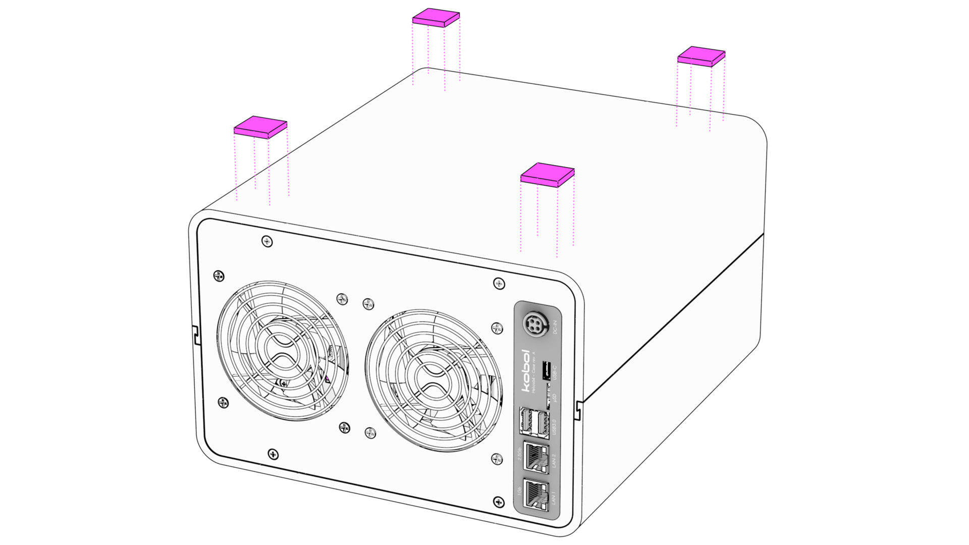
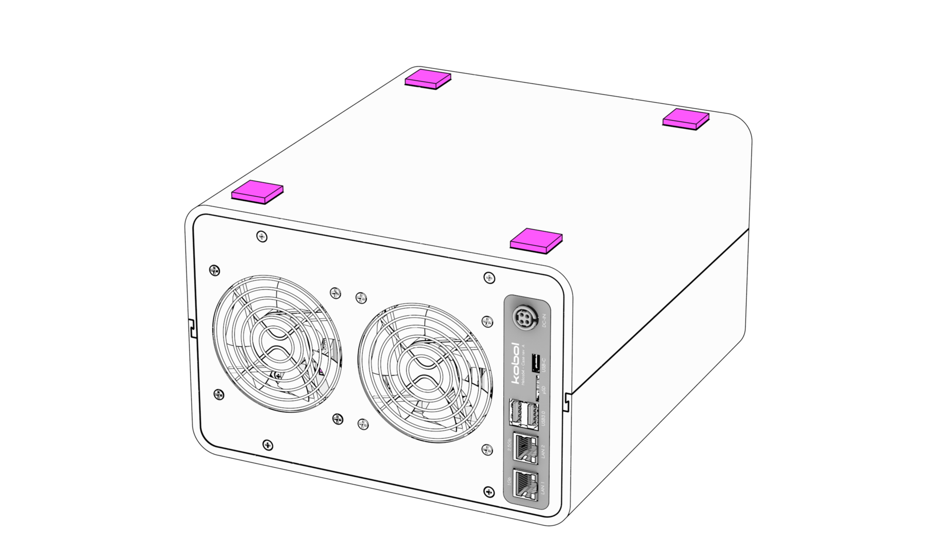
Install 4x Foam Pads on the bottom side of the enclosure
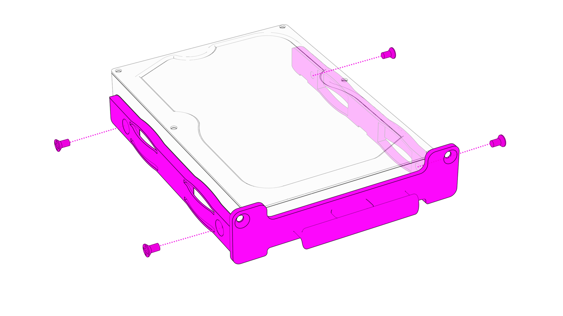
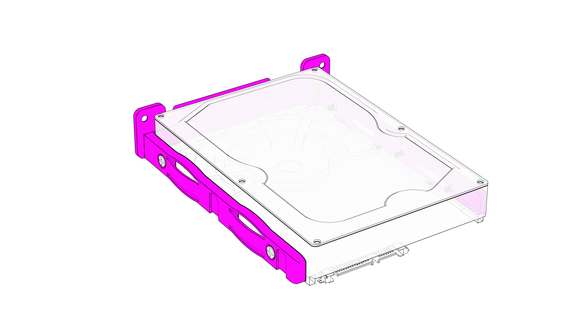
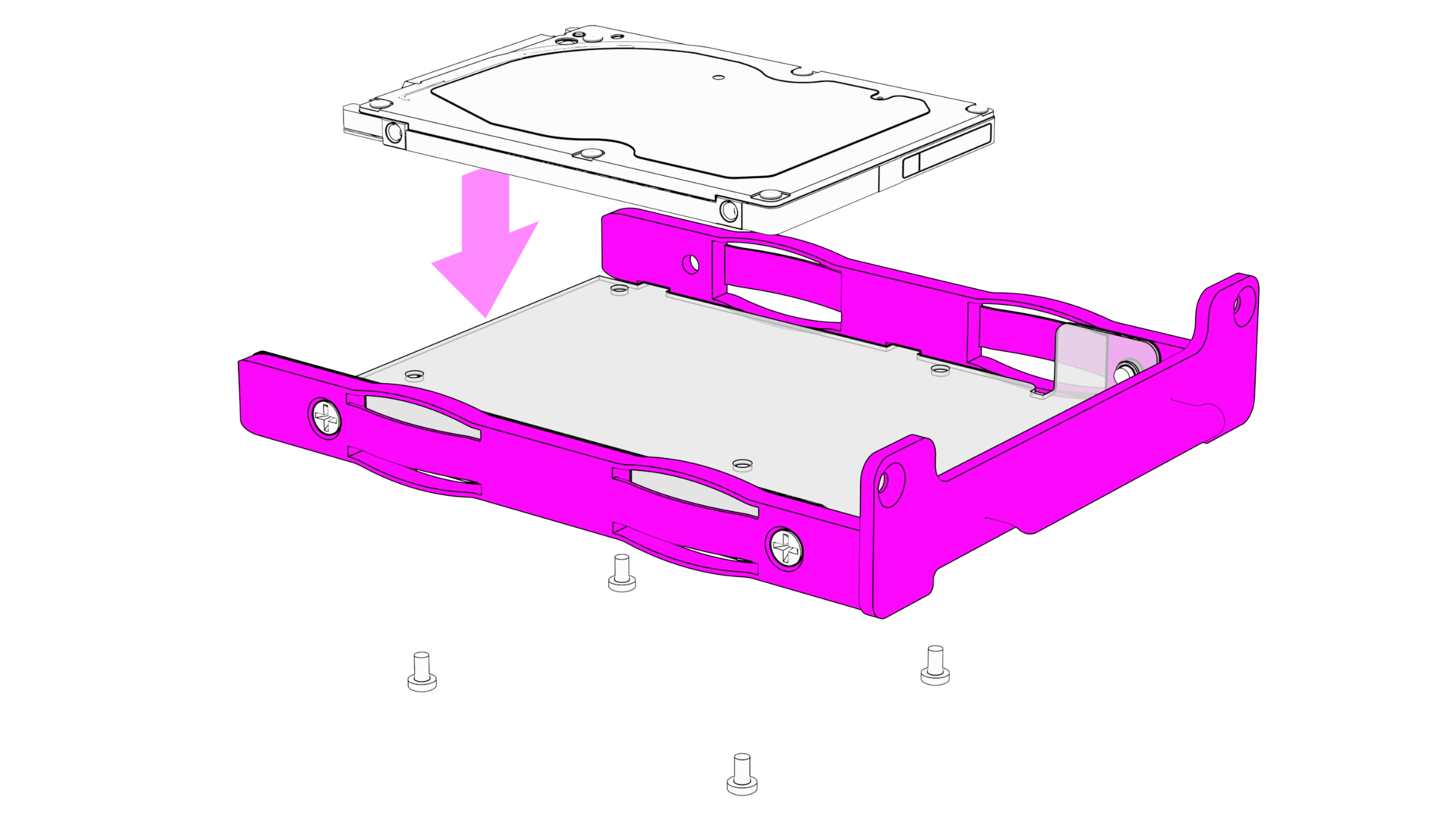
STEP 9 - Prepare HDD Trays
Secure the pink plastic Tray around the HDD with 4x screws (6/32" UNC Flat Head).
Important
The HDD connector should be on the opposite side of the plastic Tray handle.
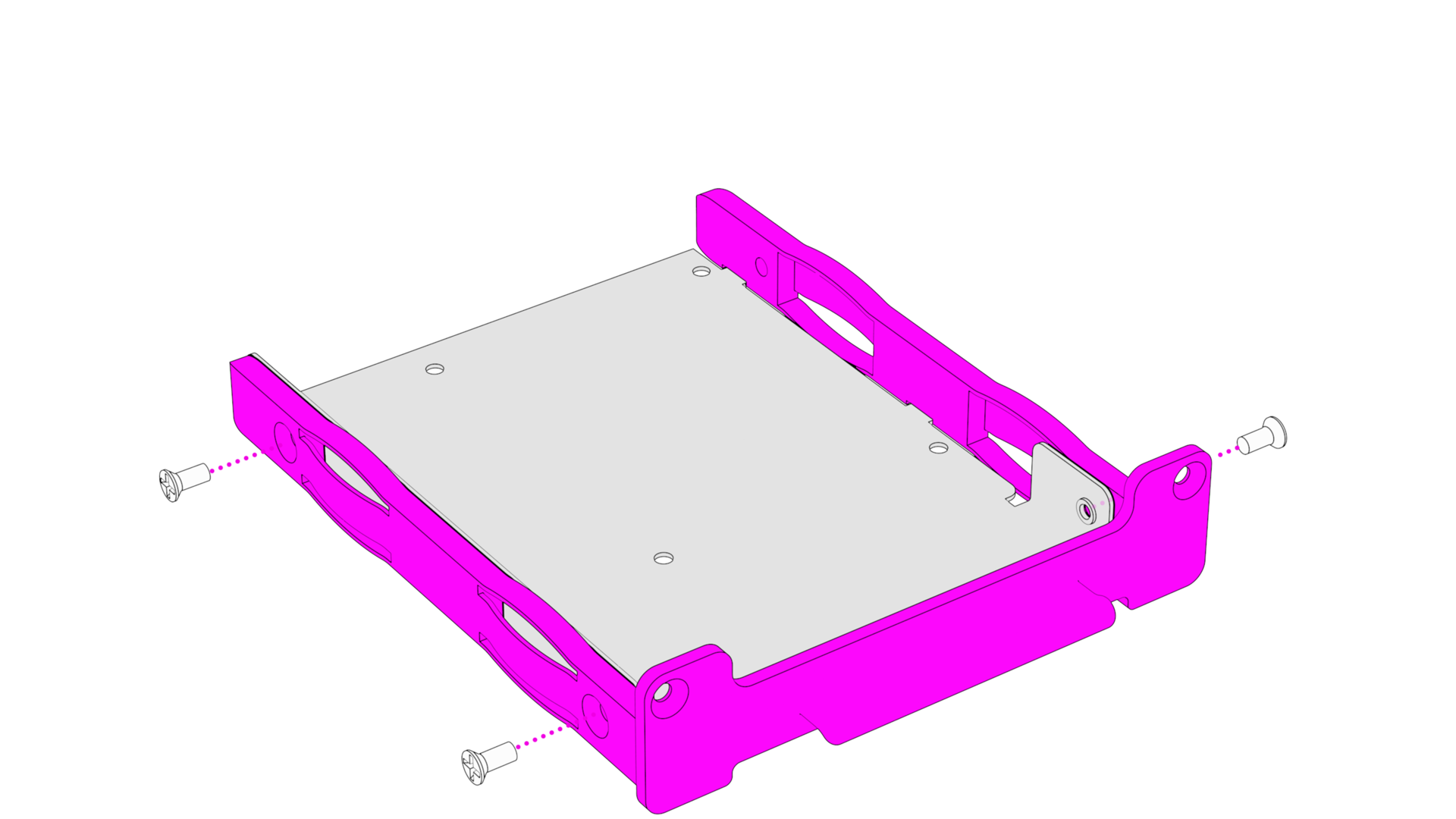
STEP 10 - Use 2.5" Adapter (Optional)
Push-in plastic Tray in metal Adapter.
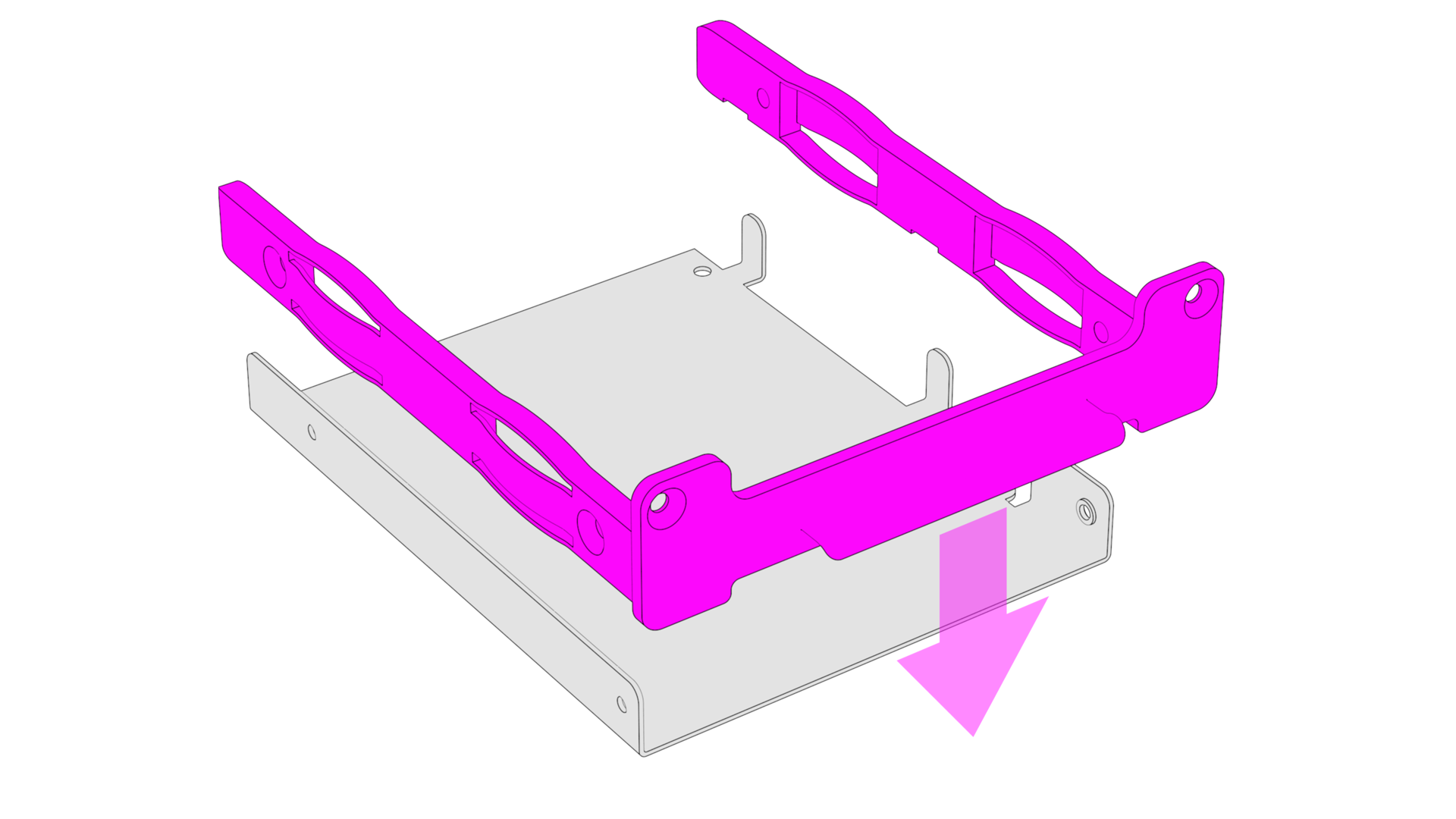
Secure metal Adapter to plastic Tray with 3x screws (6/32" UNC Flat Head)
Install 2.5" HDD/SSD according to mounting holes and use the 4x screws provided with the adapter (M3 x 3mm Flat Head).
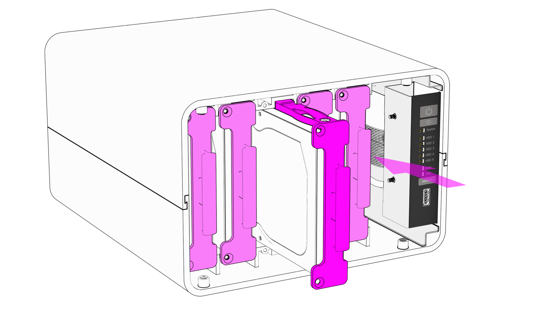
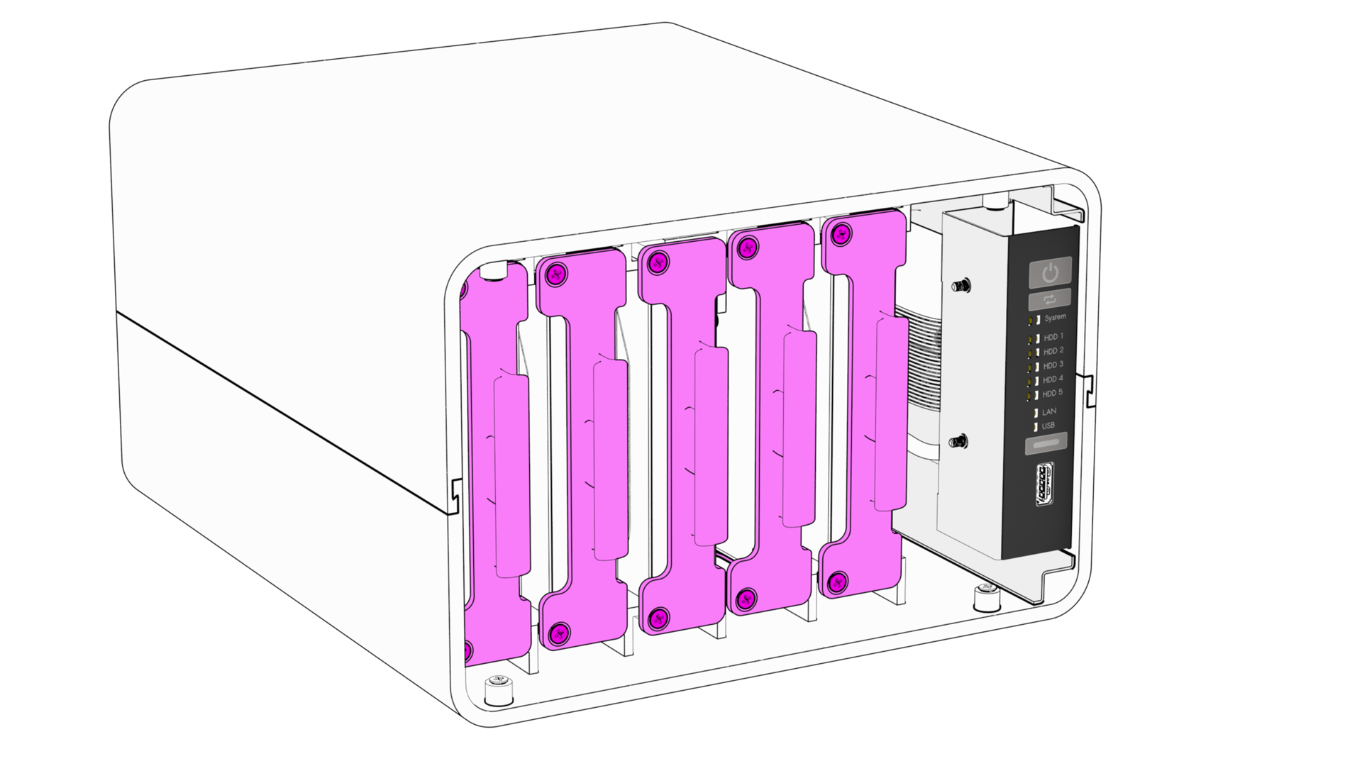
STEP 11 - Finish Assembly
Slot in the HDD Trays.
Important
- Pay attention to the orientation, you don't want to damage the SATA connectors when inserting the Trays.
- The plastic Trays might feel difficult to insert at first. They will loosen up a bit with time.
Note
Slot numbering starts from left with Slot 1 (SATA Port 1). You can use provided Number stickers to identify each HDD Trays.
If required you can secured each HDD tray to the enclosure with 2x screws (M3 x 8mm Flat Head)
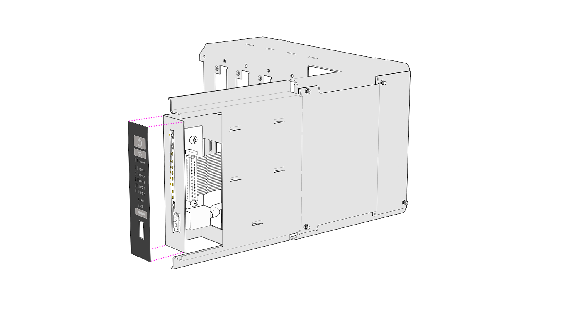
Install the Front Panel.
Note
The Front Panel should hold by itself thanks to the 4x pre-installed round magnets.
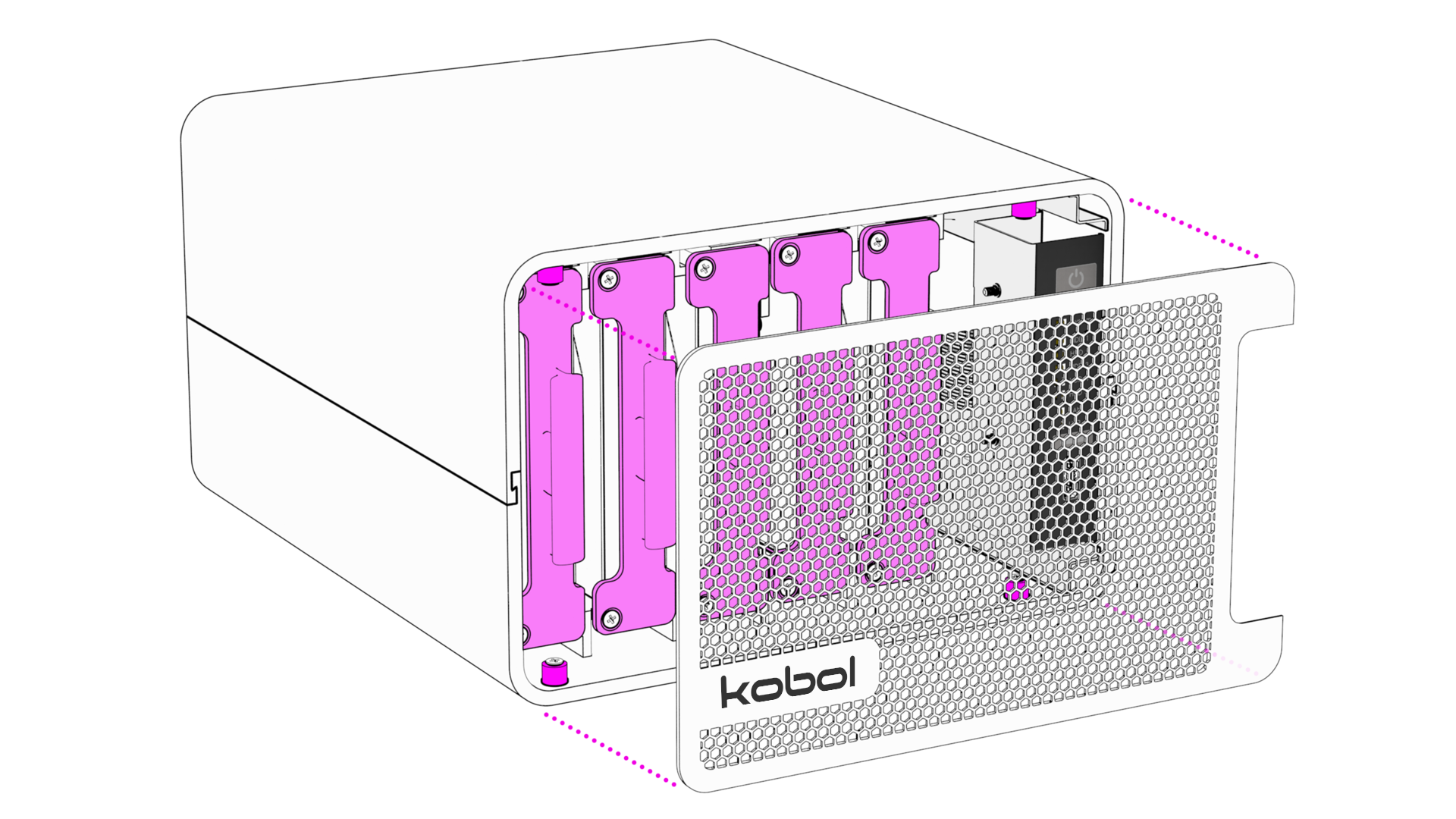
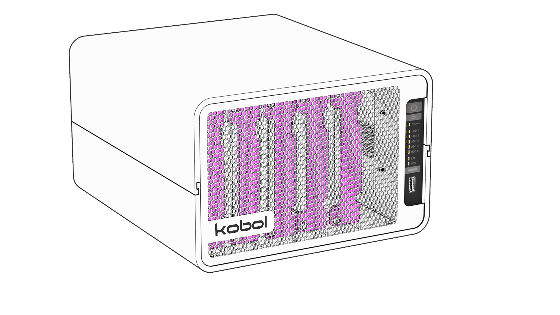
Helios64 Enclosure Kit Assembly Completed !
Now you can jump to the install section.
3D drawings made by Kites Design