Overview
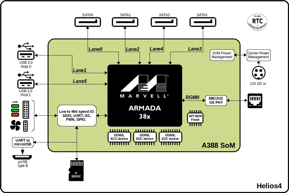
Block Diagram
Helios4 Carrier Board
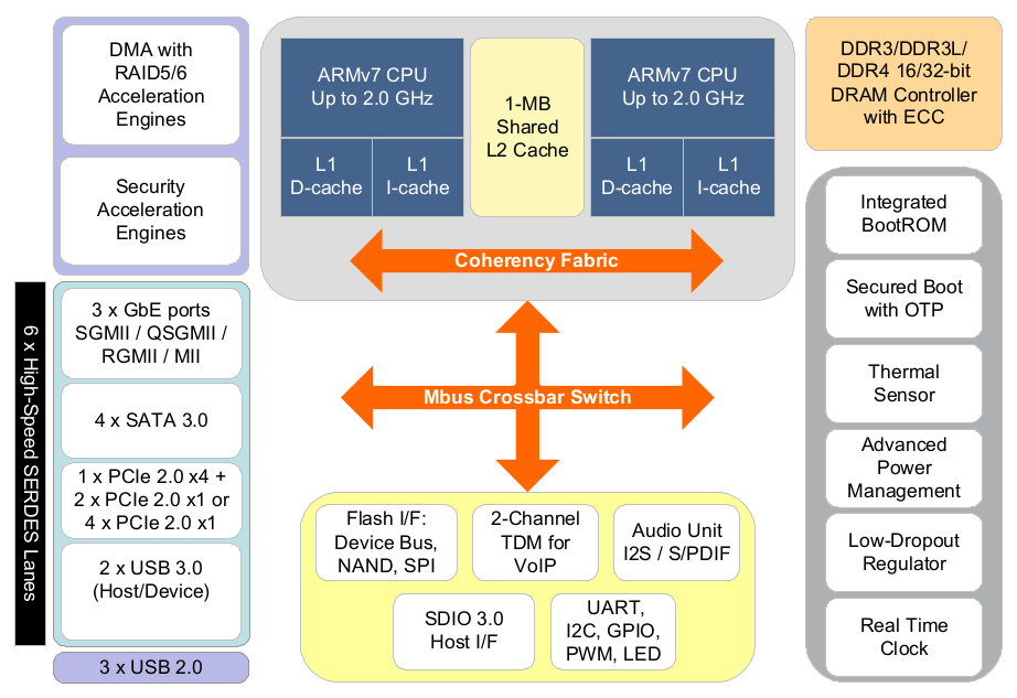
A388 System-On-Chip
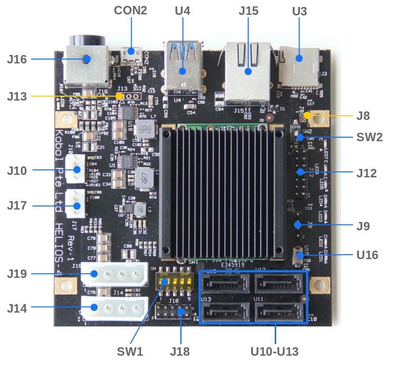
Connector / Interface List
| Name | Peripheral Type | Connector Type | Details |
|---|---|---|---|
| CON2 | Serial port | Micro-USB Connector | Via onboard FTDI USB-to-UART0 bridge |
| J8 | RC Battery | Not populated | External battery source for RTC clock |
| J9 | I2C | 4x1 Pin Male Header | I2C Bus 1 |
| J10 | Fan | 4x1 Pin Male Header | PWM and RPM support |
| J12 | GPIO | 7x2 Pin Male Header | GPIO configurable as input or output Via IO Expander on I2C Bus 0 |
| J13 | Serial port | Not populated | SoM UART0 interface |
| J14 | HDD Power | Molex 4-Pin Female | Rated for 2x HDD |
| J15 | LAN | RJ45 | Gigabit Ethernet |
| J16 | DC connector | Kycon 4-Pin Mini-DIN | DC input 12V / 8A |
| J17 | Fan | 4x1 Pin Male Header | PWM and RPM support |
| J18 | LED Panel | 5x2 Pin Male Header | Expansion port of on-board LED |
| J19 | HDD Power | Molex 4-Pin Female | Rated for 2x HDD |
| SW1 | Boot Mode | Dip Switch | Boot mode selector : SPI,MMC,UART,SATA |
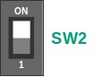
| SW2 | LED Mode | Dip Switch | LED mode selection : board or expansion panel |
| U3 | microSD | Push-Push card connector | Support SDHC and SDXC |
| U4 | USB 3.0 | Dual Port USB3.0 | Type A |
| U16 | Reset | Push Button | CPU Reset |
| U10 | SATA | SATA 3.0 | Port 0 (SATA1) |
| U11 | SATA | SATA 3.0 | Port 1 (SATA2) |
| U12 | SATA | SATA 3.0 | Port 2 (SATA3) |
| U13 | SATA | SATA 3.0 | Port 3 (SATA4) |
Boot Modes
Helios4 supports 4 boot modes that can be chosen by using the dipswitch SW1.
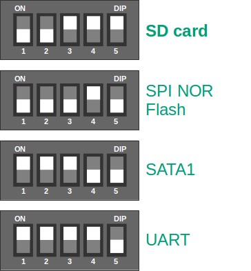
All the ready-to-use images we provide are for the SD Card boot mode.
Please refer to U-boot section to know how to use the other modes.
LED indicators
| LED Name | Color | Description |
|---|---|---|
| LED1 | green | System heartbeat |
| LED2 | red | Error status |
| LED3 | green | SATA1 activity |
| LED4 | green | SATA2 activity |
| LED5 | green | SATA3 activity |
| LED6 | green | SATA4 activity |
| LED7 | green | USB activity |
| LED8 | green | Power indicator |
Helios4 board was designed to either use the on-board LEDs or use an expansion panel (not-available). To use the on-board LEDs insure to switch to ON the dipswitch SW2.
Reset Button
Helios4 board provides a RESET push button (U16) to hard reset the SoC (System-On-Chip).
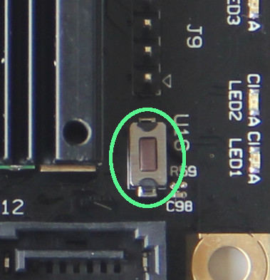
Important
This button only resets the SoC and not the overall board. For instance it won't reset the HDD.
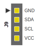
I2C Interface
Helios4 board exposes on header J9 the SoC I2C Bus 1. Below is the header pin-out, the little arrow on the PCB indicates the ground pin.
Power Consumption
Board only
- Idle : 3.6 Watts
- Active : 5.6 Watts
Full Kit (with 4x HDDs)
| State | AC calculated power consumption |
DC measured power consumption |
Remarks |
|---|---|---|---|
| Idle | 19.3 W | 16.8 W | |
| HDD Read Access | 27.4 W | 22.8 W | |
| HDD Write Access | 30.3 W | 25.2 W | |
| Standby | 8.0 W | 6.7 W | HDD in Standby mode |
| Suspend-to-Ram | 7.2 W | 6.0 W | HDD in Standby mode |
Note
Measures were done using a Current Clamp Meter on the Helios4 12V DC input. AC Power consumption is calculated based on a AC/DC conversion efficiency of 85%.
- Meter tool : Extech 380942 - 30A True RMS AC/DC Mini Clamp
- AC/DC Adapter : yczx1268 (efficiency : 85%)
- AC Input Voltage: 220V
- HDD: 4x WD Red 2TB (WD20EFRX) configured as RAID10
- Network : Connected at 1000Mb/s
- OS: ARMBIAN 5.73 stable Debian GNU/Linux 9 (stretch) 4.14.98-mvebu
HDD Recommendation List
We recommend HDD which are designed for NAS (Network Attached Storage). Those NAS HDD are specially conceived for reliable 24/7 operation and offers lower power consumption and dissipation, less vibration and noise, and finally better warranty. We recommend the following brands / families :
- Western Digital : WD Red NAS
- Seagate : IronWolf NAS
- HGST : Deskstar NAS
- Toshiba : NAS N300
Note
We recommend to order from different shop to avoid having all the drives from the same factory batch. For instance, you should order 2x HDDs from one shop, then the 2 others from another shop.