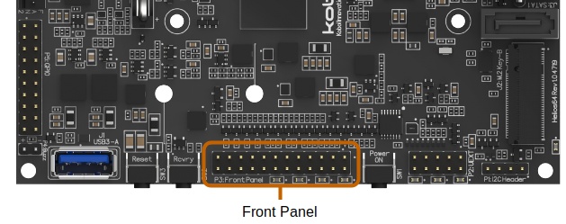
Front Panel
Helios64 provides an external front panel interface via a 24-Pin header (P3) in order to expose system buttons and LEDs.
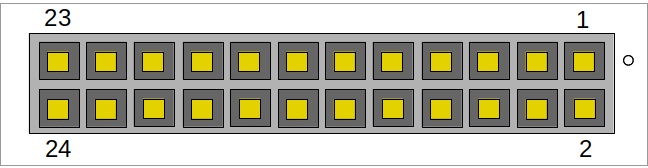
Pinout
| PIN | Port | Direction |
|---|---|---|
| 1 | SATA Consolidated Activity LED | |
| 2 | Power On LED | |
| 3 | Ground | |
| 4 | Ground | |
| 5 | RESET Button | |
| 6 | POWER Button | |
| 7 | USR1 Button | |
| 8 | USR2 Button | |
| 9 | Network Activity LED | |
| 10 | USB Activity LED | |
| 11 | 3V3 | |
| 12 | System On LED | |
| 13 | System Error LED | |
| 14 | SATA 0 Activity LED | |
| 15 | SATA 0 Error LED | |
| 16 | SATA 1 Activity LED | |
| 17 | SATA 1 Error LED | |
| 18 | SATA 2 Activity LED | |
| 19 | SATA 2 Error LED | |
| 20 | SATA 3 Activity LED | |
| 21 | SATA 3 Error LED | |
| 22 | SATA 4 Activity LED | |
| 23 | SATA 4 Error LED | |
| 24 | Ground |
Wiring Example
LED wiring:
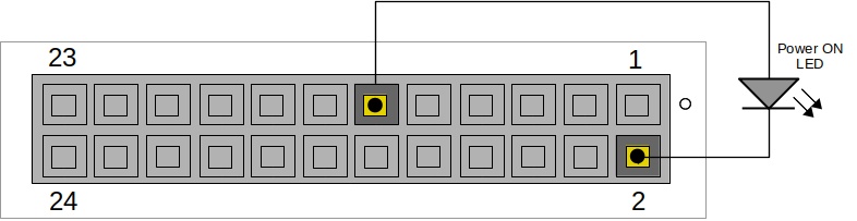
LED output pins are Active High.
Button wiring:
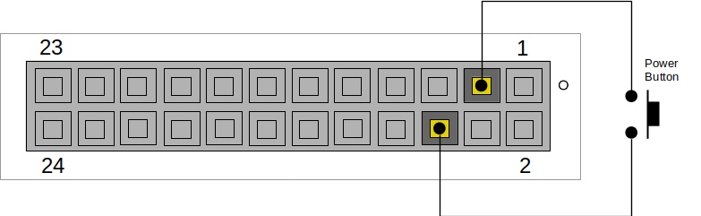
Button input pins are Active Low.
Helios64 Enclosure
The official Helios64 enclosure comes with a specially designed front panel that connects to the 24-Pin header (P3) and USB 3.0 Port (J1). This front panel exposes all the on-board LEDS and Buttons required to operate the Helios64 NAS along with an USB 3.0 port for data loading / offloading.
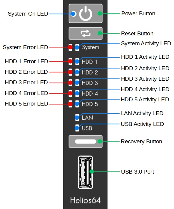
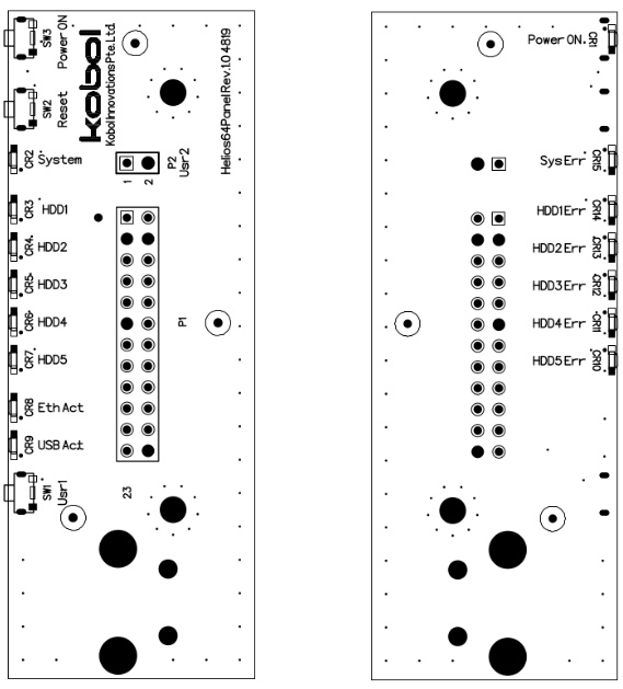
PCB Details
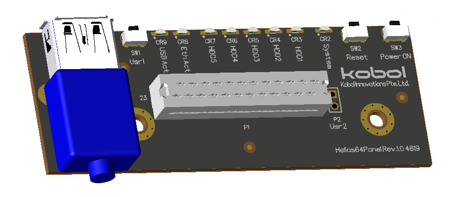
- All switches are push buttons.
- All Error LEDs are red while Status / Activity LEDs are blue.
- USB 3.0 Port is provided by a USB 3.0 Type A Female to Male extension cable.
PCB Wiring
The Helios64 Front Panel is already mounted with the USB 3.0 extension cable and with a ribbon cable + header snapped to the ICD connector (P1).
The wiring between Helios64 main board and the front panel is illustrated in figures below:
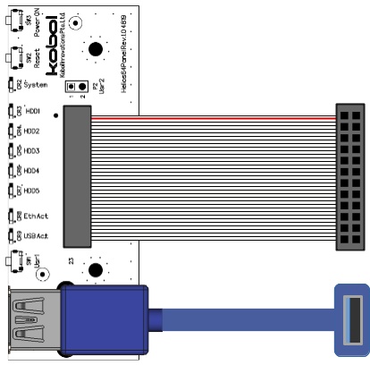
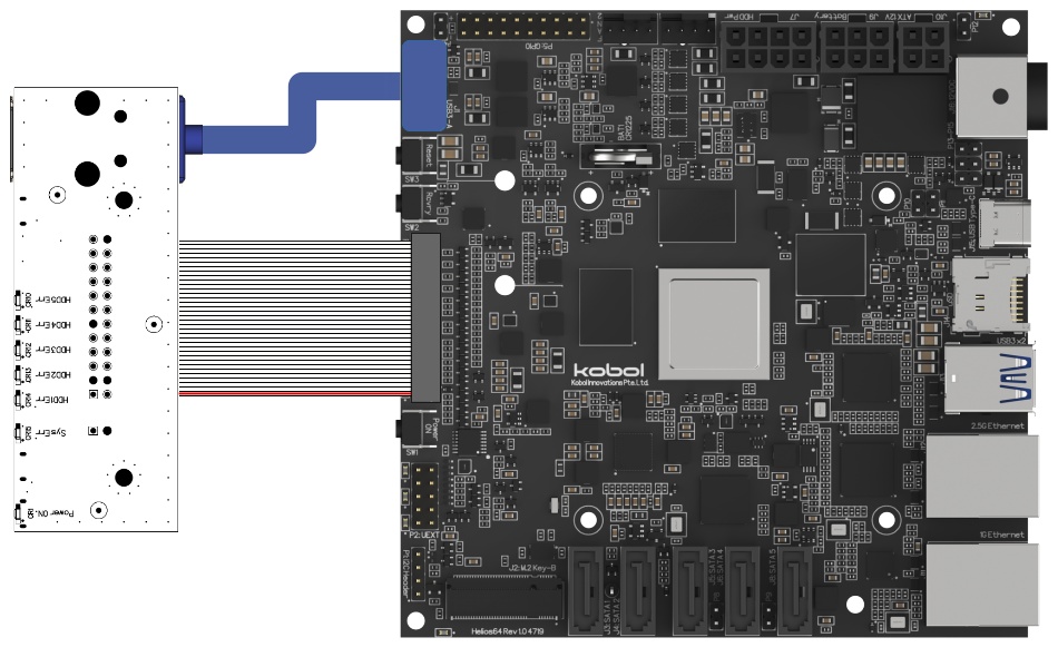
Warning
Please be careful with the 24-Pin header polarity. Make sure that Pin 1 of main board P3 header is connected to the Pin 1 of front panel P1 ICD connector.